
Left atrial appendage occlusive devices

a technology of occlusive devices and atrial fibrillation, which is applied in the field of left atrial appendage occlusive devices, can solve the problems of low cardiac output, irregular and turbulent blood flow in the vascular system, and the patient with atrial fibrillation typically has a significantly decreased quality of li

Active Publication Date: 2014-12-25
WL GORE & ASSOC INC
View PDF13 Cites 7 Cited by
  • Summary
  • Abstract
  • Description
  • Claims
  • Application Information

AI Technical Summary

Benefits of technology

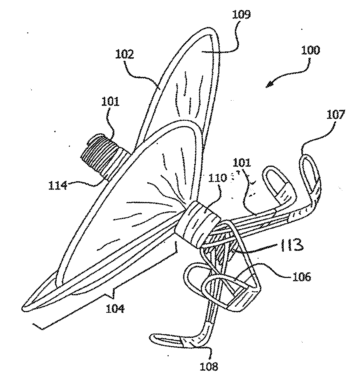
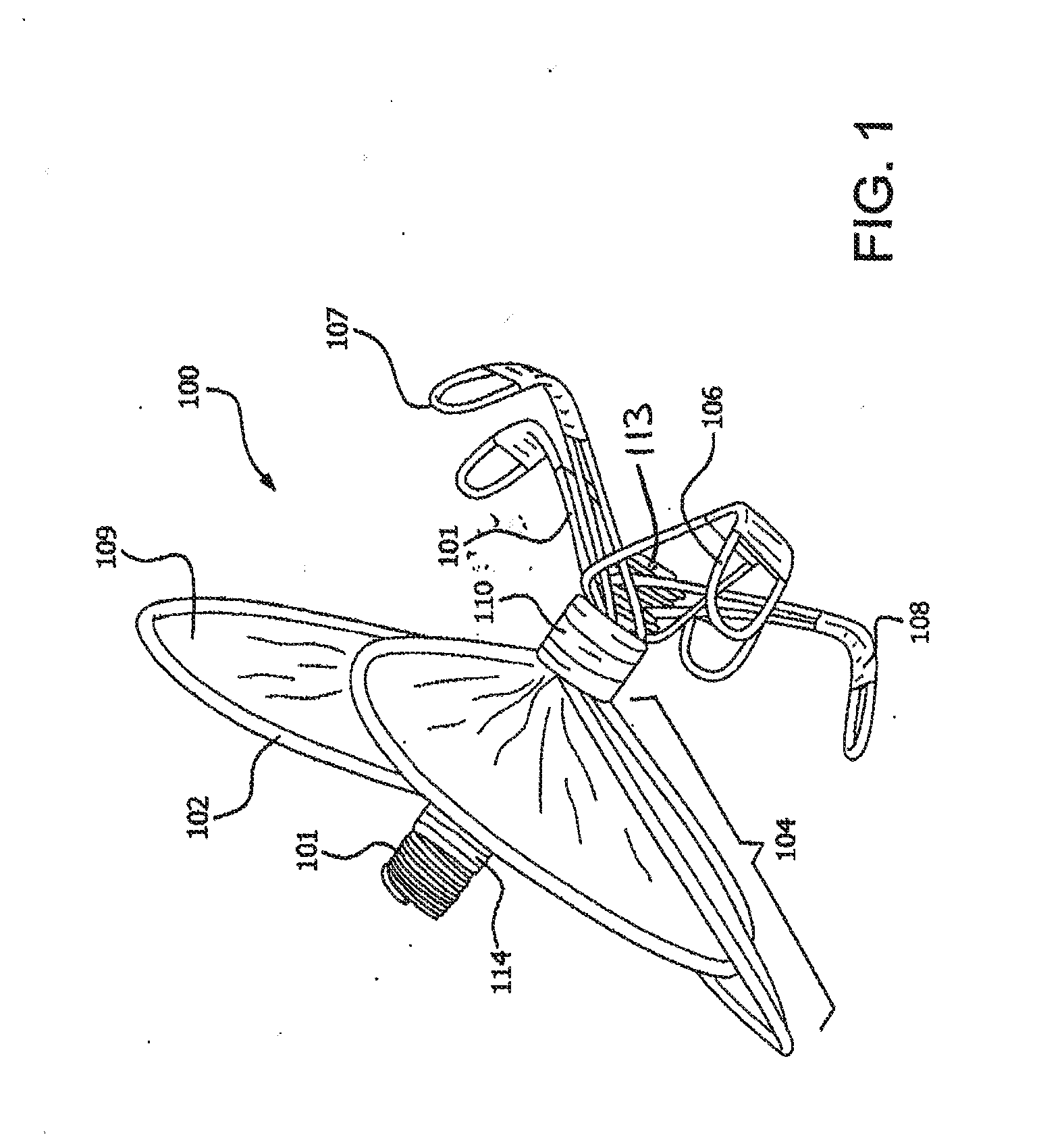
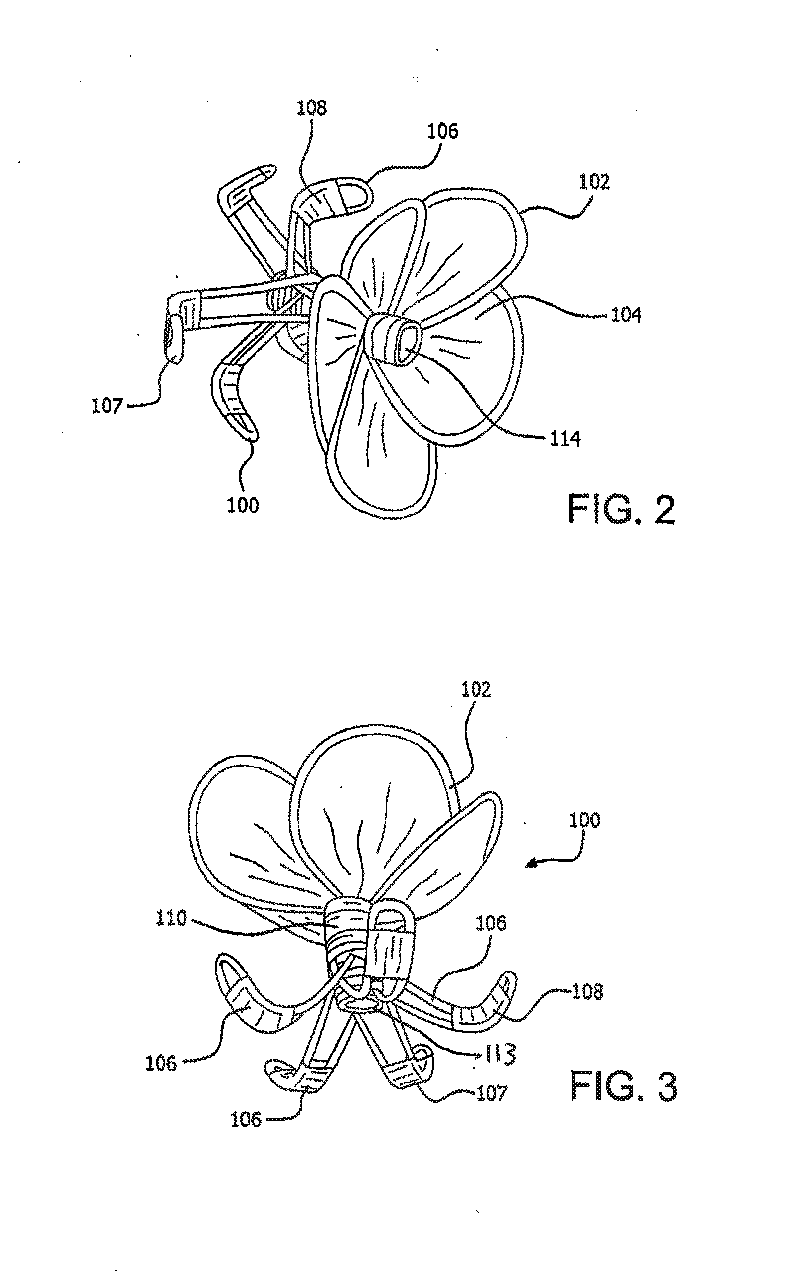
The patent describes a new type of occlusive device that can be used to prevent blood from flowing through certain parts of the body. The device consists of a membrane component and an expandable frame made up of wires. The membrane component is placed at the beginning of the device and is designed to prevent blood from passing through it. The expandable frame is attached to the membrane component and is made up of wires. The frame has a unique shape and is designed to be expanded when it is released from its natural state. The device can be used to treat various medical conditions that require the prevention of blood flow.

Problems solved by technology

Embolic stroke is the nation's third leading killer, and is a major cause of disability.
Atrial fibrillation is the most common heart arrhythmia; it results in a rapid and chaotic heartbeat that lowers cardiac output and leads to irregular and turbulent blood flow in the vascular system.
A patient with atrial fibrillation typically has a significantly decreased quality of life due, in part, to the fear of stroke, and the pharmaceutical regimen necessary to reduce that risk.
However, with atrial fibrillation, the left atrial appendage often fails to contract with any vigor due to the disorganized electrical signals.
Pharmacological therapies for stroke prevention in atrial fibrillation patients such as oral or systemic administration of warfarin have often been inadequate due to serious side effects and lack of patient compliance.
Invasive surgical or thorascopic techniques have been used to obliterate the left atrial appendage, however, many patients are not suitable candidates for such procedures due to compromised condition or previous cardiac surgery.
In addition, the perceived risks of these surgical procedures often outweigh the potential benefits.
These devices have a number of issues and / or potential drawbacks.
Sealing the left atrial appendage with a rigid frame that presupposes a circular ostium can be less effective at preventing thromboemboli from entering systemic circulation.
The tissue of the left atrial appendage is generally fragile and thin.
This makes bleeding from the heart through the holes caused by the tissue-piercing fixation members into the pericardial space a potentially life-threatening situation due to the potential for tamponade (compression of the heart when blood or fluid builds up in the space between the myocardium (heart muscle) and the pericardium (outer covering sac of the heart)).
These membranes are macroporous and do not provide immediate cessation of blood flow through the membrane.
Such membranes can take hours to weeks to substantially occlude.
Many of these atrial fibrillation patients are on some type of blood thinning (anticoagulant or antiplatelet) medication, which could prolong the clotting / occluding process for these filtering membranes and expose patients to stroke risk.

Method used


Image

  • Left atrial appendage occlusive devices
  • Left atrial appendage occlusive devices
  • Left atrial appendage occlusive devices

Examples


example 1

[0124]An about 1 meter length of 10% platinum drawn filled nitinol wire (Fort Wayne Metals, Fort Wayne, Ind.) with a diameter of about 0.23 mm is obtained. The specific length of the wire may or may not be measured, but the wire should be long enough to complete the winding pattern as described in the following paragraph. The wire is obtained having been electropolished. Electropolishing nitinol wire imparts certain well known properties, such as spontaneously forming a titanium dioxide layer on the surface, selectively reducing the amount of nickel on the surface of the wire, and removing some of the stresses in the wire thus improving fatigue.

[0125]A base jig 8 as described in FIG. 11 is obtained. A knot is tied into one end of one length of an about 0.5 meter long wire and the unknotted end is fed through a wire feed hole 10. Two additional lengths of wire (about 1 meter each) are folded in half and the free ends are fed through the remaining four feed holes 12, 14, 16, 18, with ...

example 2

[0158]An article is constructed in the same manner, using the same materials, as Example 1 with the following exceptions. The film tube is not applied as a tube, but rather it is slit longitudinally and the resulting flat sheet is used to cover the nitinol frame. Without tensioning the occlusive member, the sheet is draped over the top frame petals and the edges of the sheet are gathered and secured around the center eyelet. The occlusive component of the resulting article has a cupped occlusive component with a flat proximal surface and a cupped distal surface as shown in FIG. 9.

example 3

[0159]An article is constructed in the same manner, using the same materials, as Example 1 with the following exceptions. The cupped occlusive member and the anchor component are detached from each other by clipping the center eyelet by hand. An ePTFE tube with a diameter similar to that if the outer diameter of the eyelet shown in FIGS. 19A-19B is procured and secured to the distal eyelet of the cupped occlusive member and the proximal eyelet of the anchor component. The tube is secured by overwrapping tape containing FEP as previously described.


PUM


Abstract

An occlusive device for left atrial appendage occlusion that has a membrane component configured to inhibit passage of blood and an expandable frame formed from a plurality of wires having a cupped occlusive component at least partially covered with the membrane component, one or more anchors with looped ends and a hub component. The occlusive device can be delivered percutaneously. The occlusive device is useful in the occlusion of the left atrial appendage.

Description

FIELD OF THE INVENTION[0001]The present invention relates to occlusive devices useful, for example, in occluding structures or conduits within a patient, particularly an atrial appendage in the human heart. Devices of the present invention can be delivered percutaneously or in an endovascular fashion.BACKGROUND OF THE INVENTION[0002]Embolic stroke is the nation's third leading killer, and is a major cause of disability. There are over 780,000 strokes per year in the United States alone. Of these, roughly 110,000 are hemorrhagic, and 670,000 are ischemic (either due to vessel narrowing or to embolism). The most common cause of ischemic stroke of cardiac origin is thromboemboli due to atrial fibrillation. One out of every six strokes (approximately 130,000 per year) is attributed to atrial fibrillation. Atrial fibrillation is the most common heart arrhythmia; it results in a rapid and chaotic heartbeat that lowers cardiac output and leads to irregular and turbulent blood flow in the v...

Claims


Application Information

Patent Timeline
Patent Type & Authority Applications(United States)
IPC IPC(8): A61B17/12
CPCA61B17/1215A61B17/12145A61B17/12122A61B17/0057A61B17/12172A61B2017/00592A61B2017/00597A61B2017/00615A61B2017/00623A61B2017/00632A61B2017/1205A61B17/12A61B17/00A61M25/09A61L29/02
Inventor CAMPBELL, BENJAMIN D.CULLY, EDWARD H.DUNCAN, JEFFREY B.HELDER, NICHLAS L.LARSEN, COBY C.MASTERS, STEVEN J.MATHENA, SCOT K.MCDANIEL, THOMAS R.SHAW, EDWARD E.
Owner WL GORE & ASSOC INC
Learn More