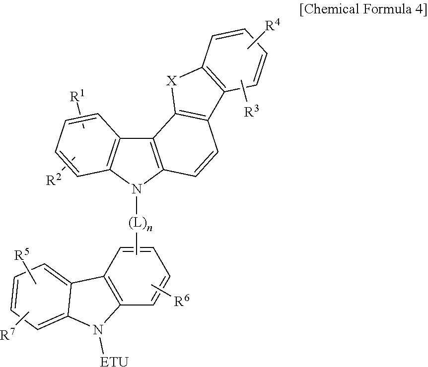
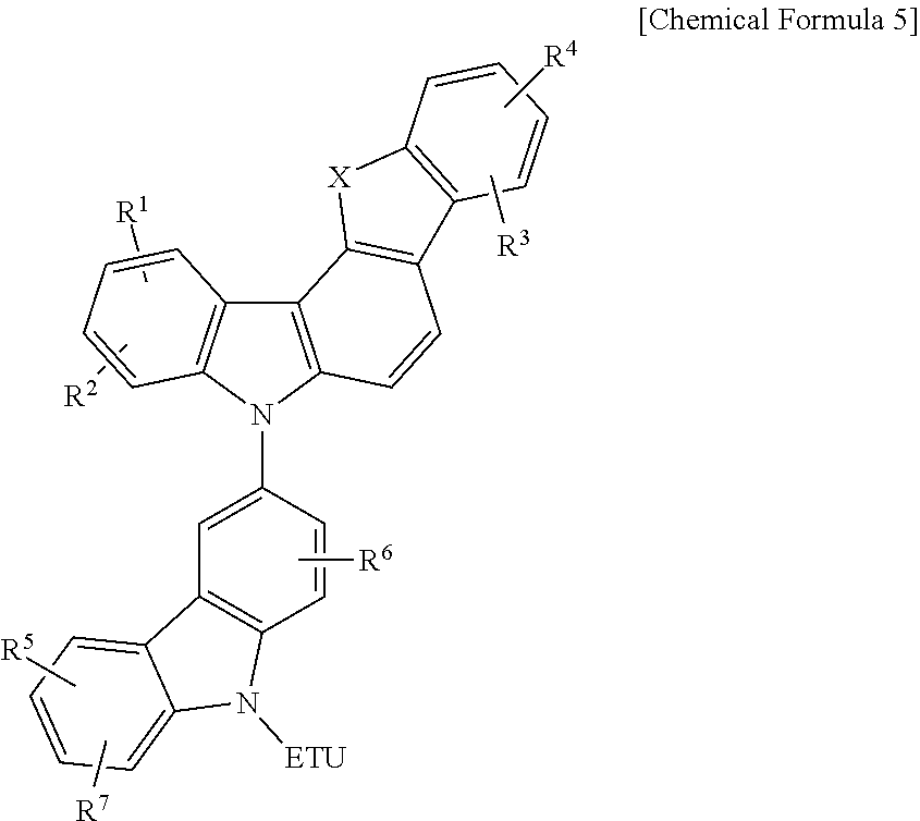
Compound for an organic optoelectronic element, organic light-emitting element comprising same, and display device comprising the organic light-emitting element
a technology of organic light-emitting diodes and organic optoelectronic elements, which is applied in the direction of thermoelectric devices, sustainable manufacturing/processing, final product manufacturing, etc., can solve the problems of inefficient combination of holes and electrons, and the development of organic material layer forming materials for organic light-emitting diodes has so far not been satisfactory, etc., to achieve high triplet exciton energy, high hole or electron transport properties, and improved life-span characteristics
- Summary
- Abstract
- Description
- Claims
- Application Information
AI Technical Summary
Benefits of technology
Problems solved by technology
Method used
Image
Examples
example 1
Preparation of Compound A-1
[0112]
[0113]23.0 g of a compound A and 14.5 g of a compound B were dissolved in 350 mL of toluene under a 1 L round-bottomed flask equipped with a thermometer, a reflux condenser, and an agitator under a nitrogen atmosphere, 13.3 g of sodium tert-butoxide (NaOtBu), 2.8 g of palladium dibenzylideneamine (Pd(0)dba2), and 2.0 g of tertiarybutyl phosphorus (a 50% solution in toluene) were added thereto, and the mixture was refluxed for 12 hours in a reactor. The resultant was naturally cooling down to room temperature and precipitated in 1.2 L of methanol and then, agitated for 1 hour. A solid produced therein was filtered and added to 1.2 L of water to prepare slurry, and the slurry was agitated for one hour and then, filtered again. The filtered solid was dried and then, dissolved in 1 L of monochlorobenzene by heating, and the solution was passed through a celite / silica pad. The passed solution was heated and concentrated down to 500 mL and then, naturally ...
example 2
Preparation of Compound B-1
[0114]
[0115]23.0 g of a compound A and 13.6 g of a compound C was dissolved in 350 mL of toluene in a 1 L round-bottomed flask equipped with a thermometer, a reflux condenser, and an agitator under a nitrogen atmosphere, 13.3 g of sodium tert-butoxide (NaOtBu), 2.8 g of palladium dibenzylideneamine (Pd(0)dba2), and 2.0 g of tertiarybutyl phosphorus (a 50% solution in toluene), and the mixture was refluxed for 12 hours in a reactor. The resultant was naturally cooled down to room temperature and precipitated in 1.2 L of methanol and then, agitated for one hour. A solid produced therein was filtered and added to 1.2 L of water to prepare slurry, and the slurry was agitated for one hour and refiltered. The filtered solid was dried and dissolved in 1 L of monochlorobenzene by heating, and then, the solution was passed through a celite / silica pad. The passed solution was heated and concentrated down to 500 mL and then, naturally cooled down to room temperature....
example 3
Preparation of Compound B-4
[0116]
[0117]22.9 g of a compound D and 13.6 g of a compound C were dissolved in 0.350 mL of toluene in a 1 L round-bottomed flask equipped with a thermometer, a reflux condenser, and an agitator under a nitrogen atmosphere, 13.3 g of sodium tert-butoxide (NaOtBu), 2.8 g of palladium dibenzylideneamine (Pd(0)dba2), and 2.0 g of tertiarybutyl phosphorus (a 50% solution in toluene) were added thereto, and the mixture was refluxed in a reactor for 12 hours. The resultant was naturally cooled down to room temperature and precipitated in 1.2 L of methanol and then, agitated for one hour. A solid produced therein was filtered and added to 1.2 L of water to prepare slurry, and the slurry was agitated for 1 hour and filtered again. The filtered solid was dried and heated and dissolved in 1 L of monochlorobenzene, and the solution was passed through a celite / silica pad. The passed solution was heated and concentrated down to 500 mL and then, naturally cooled down to...
PUM
 Abstract
Description
Claims
Application Information
 - R&D
- Intellectual Property
- Life Sciences
- Materials
- Tech Scout
- Unparalleled Data Quality
- Higher Quality Content
- 60% Fewer Hallucinations
Browse by: Latest US Patents, China's latest patents, Technical Efficacy Thesaurus, Application Domain, Technology Topic, Popular Technical Reports.
© 2025 PatSnap. All rights reserved.Legal|Privacy policy|Modern Slavery Act Transparency Statement|Sitemap|About US| Contact US: help@patsnap.com


