
Travelling cable of an elevator, and an elevator

a technology of elevator travel and travel cables, which is applied in the direction of power cables, conductors, power cables including electrical control, etc., can solve the problems of overcompensation of ropes, too large mass per meter of travelling cables implemented with steel rope bearers, and the inability to achieve optimal compensation, etc., to achieve the effect of improving energy efficiency of elevators, reducing the number of cables, and saving considerable resources

Active Publication Date: 2014-11-27
KONE CORP
View PDF10 Cites 35 Cited by
  • Summary
  • Abstract
  • Description
  • Claims
  • Application Information

AI Technical Summary

Benefits of technology

The invention aims to improve the structure of the traveling cable of a lifting device, such as a passenger transport elevator or freight transport elevator, and to use it to compensate for the movement of the elevator's ropes. The goal is to achieve better performance and efficiency.

Problems solved by technology

When using composite-structured lightweight hoisting ropes and suspension ropes, the mass per meter of travelling cables implemented with steel rope bearers is too great for implementing optimal compensation.
Travelling cables comprising steel rope bearers are too heavy for use with lightweight composite ropes, in which case overcompensation of the ropes becomes a problem.
Additionally, a problem particularly in high-rise buildings and in the high-speed elevators used in them is that at high speeds vortices occur in the elevator hoistway owing to the air resistance of the elevator car, which vortices produce lateral movement in the travelling cable of the elevator and more particularly in the bottom loop of said cable.
This type of lateral swaying is undesirable, because it increases the stressing of the travelling cable and produces noise and vibration or other discomfort to passengers of the elevator car.
In addition, large lateral movement might cause the travelling cable to strike structures of the elevator hoistway, damaging hoistway devices or itself getting caught on them.

Method used


Image

  • Travelling cable of an elevator, and an elevator
  • Travelling cable of an elevator, and an elevator
  • Travelling cable of an elevator, and an elevator

Examples


Embodiment Construction

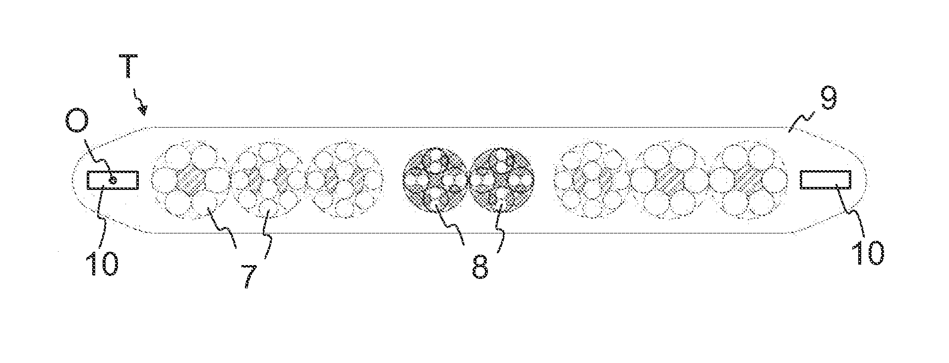
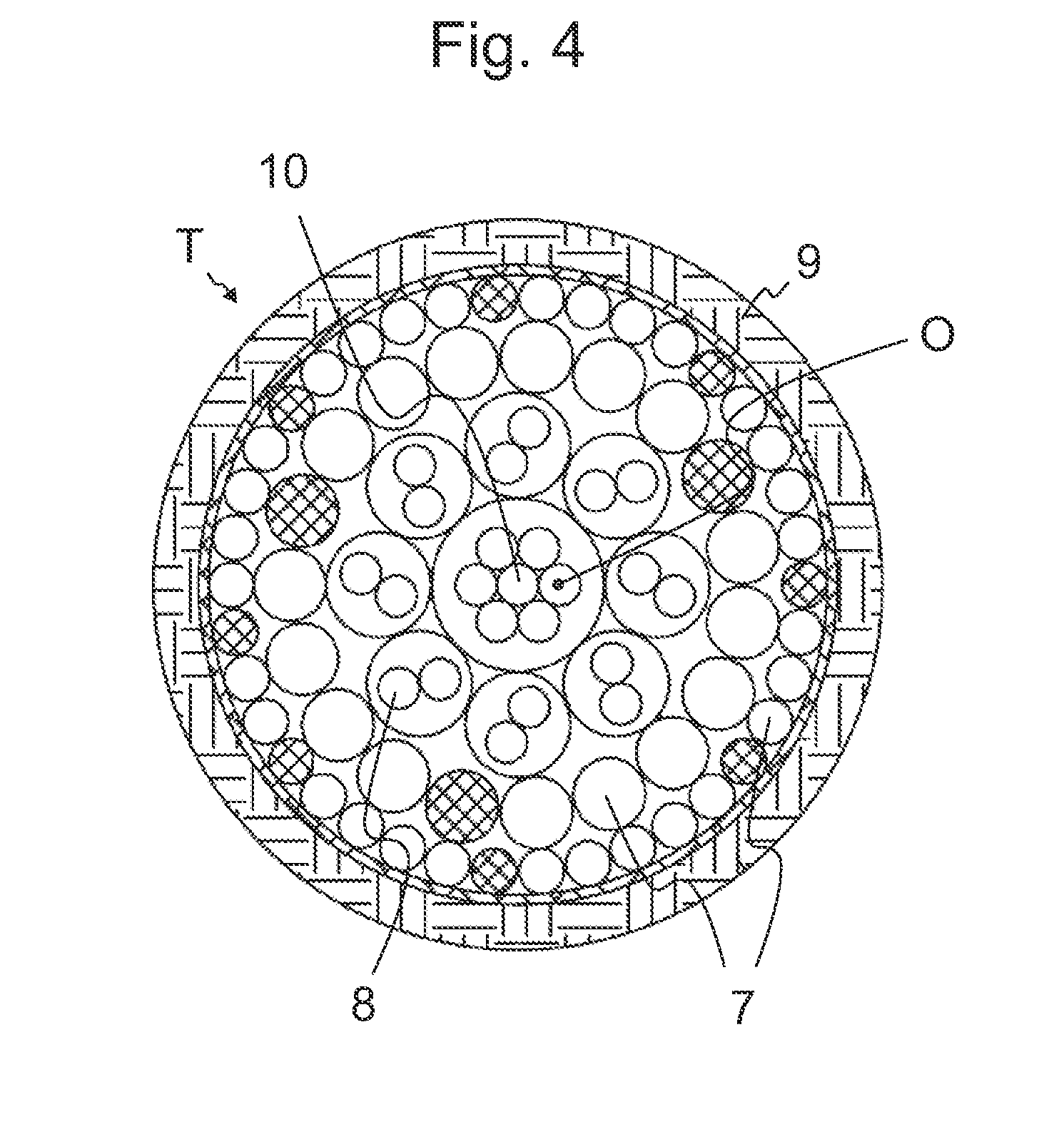
[0072]FIGS. 1 and 2 present an elevator according to the invention, which comprises an elevator car 1, a counterweight 2 and suspension roping 3, the ropes of which connect the aforementioned elevator car 1 and aforementioned counterweight 2 to each other. The elevator car 1 and the counterweight 2 are arranged to be moved by exerting a vertical force on at least the elevator car 1 or on the counterweight 2 by the aid of the means M, 6, 3, 4. The suspension roping 3 comprises one or more ropes, which comprise a load-bearing composite part, which comprises reinforcing fibers in a polymer matrix. The elevator is preferably a passenger transport elevator and / or freight transport elevator, which is installed to travel in an elevator hoistway S in a building.

[0073]In the embodiment presented in FIG. 1, the means for exerting a force on at least the elevator car 1 or counterweight 2 comprise suspension roping 3, which is connected to the elevator car and / or to the counterweight, and a hoi...


PUM

PropertyMeasurementUnit
tensile strengthaaaaaaaaaa
densityaaaaaaaaaa
diameteraaaaaaaaaa

Abstract

A travelling cable of an elevator, more particularly of a passenger transport elevator and / or freight transport elevator, includes a protective envelope, conductors for transmitting electrical energy and data between the elevator car and the elevator hoistway, and one or more load-bearing bearer parts of essentially the length of the travelling cable for fixing the travelling cable at its first end to the elevator car and at its second end to the elevator hoistway, and which bearer part includes glass-fiber reinforcements and / or aramid-fiber reinforcements and / or carbon-fiber reinforcements and / or polybenzoxazole-fiber reinforcements and / or polyethylene-fiber reinforcements and / or nylon-fiber reinforcements in a polymer matrix material. An elevator includes the travelling cable.

Description

FIELD OF THE INVENTION[0001]The object of the invention is a travelling cable of an elevator as defined in the preamble of claim 1, and an elevator as defined in the preamble of claim 13.BACKGROUND OF THE INVENTION[0002]It is advantageous to manufacture the ropes of lifting devices, more particularly the hoisting ropes and suspension ropes of passenger transport and freight transport elevators, to be of a composite structure. When basing the longitudinal load-bearing capability of ropes on non-metallic material, more particularly on non-metallic reinforcing fibers, the ropes can be lightened and as a result of the roping being lightweight the energy efficiency of the elevator can be improved. By forming the rope to be composite-structured and belt-type, considerable savings can be achieved even though the inexpensive metal material conventionally used in the ropes of an elevator is replaced with more expensive material.[0003]A travelling cable is fixed to the car of a passenger tran...

Claims


Application Information

Patent Timeline
Patent Type & Authority Applications(United States)
IPC IPC(8): B66B7/06H01B11/22H01B7/18B66B9/00H01B9/00
CPCB66B7/064B66B9/00H01B11/22H01B7/182H01B9/003D07B1/02D07B1/025D07B1/145D07B1/147D07B1/162D07B1/165D07B1/22D07B2201/2096D07B2205/2042D07B2205/2046D07B2205/205D07B2205/2096D07B2205/3003D07B2205/3007D07B2501/2007B66B7/1238D07B2801/10
Inventor ALASENTIE, PENTTIKERE, PETRIPURANEN, MIKKO
Owner KONE CORP
Learn More