Method and device for checking the correct functioning of a serial data transmission

a serial data and correct functioning technology, applied in the field of serial data transmission methods and devices, can solve the problems of limiting the allowable bit length in the can at the lower end, affecting the accuracy of serial data transmission, and inability to shorten the related art easily, so as to achieve the effect of increasing the accuracy of time delay ascertainment, facilitating data transmission per unit time, and increasing the data volum

Active Publication Date: 2014-11-13
ROBERT BOSCH GMBH
View PDF16 Cites 35 Cited by
  • Summary
  • Abstract
  • Description
  • Claims
  • Application Information

AI Technical Summary

Benefits of technology

[0017]The messages which are to be checked using the method according to the present invention are advantageously identified by a suitable identifier, since the devices according to the present invention which exchange the messages may thus recognize whether the communication takes place according to the method according to the standard or the method according to the present invention. When this identifier is present, in one advantageous aspect the control field of the messages has more than six bits. It may thus be set up that the identification is provided by a recessive bit, which is followed by at least one dominant bit in all data messages. In this case, this edge between the recessive bit of the first identifier and the at least one subsequent dominant bit may be used for ascertaining the time offset between the undelayed transmission signal and the reception signal, which has the advantage that the accuracy of the ascertainment of the time delay is thus increased, in particular when the edges from “recessive” to “dominant” are particularly steep.
[0018]A simultaneous expansion of the data field of the messages according to the present invention to more than eight bytes has the additional advantage that larger data volumes may be transmitted within a message, and the ratio of useful data to protocol-relevant control data advantageously changes. For establishing the size of the data field, the values of the four bits of the data length code are then be interpreted differently from the CAN standard, at least in part.
[0019]Another advantage of the method according to the present invention results when in addition the bit length for at least one predefined or predefinable area within the message assumes a value that is shorter than the bit length previously used. A particular advantage of the method here is that bit lengths below the intrinsic time delay of the bus connection unit may also be used. Without the compensation according to the present invention, in this case the comparison between the undelayed transmission signal and the reception signal would erroneously result in recognition of a transmission error. Messages modified in this way may be made recognizable by a second identifier. In addition, the data volume transmitted per unit time may be further increased by this modification. The area advantageously begins at the earliest with the second identifier, and ends at the latest with the CRC delimiter. The different values of the bit length are advantageously implemented by using different scaling factors (prescalers) for setting the bus time unit relative to a smallest time unit or the oscillator clock pulse. The robustness of the method is further increased when different values for the bit timing parameters are used in the areas having a longer and a shorter bit length.
[0020]The second identifier has the advantage that the advantages of the two measures may also be utilized separately. For example, even when the switchover to a shorter bit length is not possible for reasons of the bus topology, in addition messages according to the method according to the present invention may be checked and sent at a higher data volume. Even when errors occur in messages having a shortened bit length, a switchover is initially made to the normal bit length without sacrificing the further advantages.
[0021]The method is advantageously usable during normal operation of a motor vehicle for transmitting data between at least two control units of the motor vehicle which are connected via a suitable data bus. However, the method is likewise advantageously usable during manufacture or maintenance of a motor vehicle for transmitting data between a programming unit, which for purposes of programming is connected to a suitable data bus, and at least one control unit of the motor vehicle which is connected to the data bus. Another advantageous field of application is in the operation of industrial control systems, in particular for long connecting lines. In all cases, the flexibility in the transmission rate is advantageous when at the same time there is very high transmission security, in order to adapt the transmission process to the particular conditions such as signal propagation times.
[0022]Another advantage is that only minimal changes have to be made to a CAN standard controller in order to operate according to the present invention. A communication controller according to the present invention, which may also operate as a CAN standard controller, is only insignificantly larger than a conventional CAN standard controller. The associated application program does not have to be changed, and advantages are even achieved in the speed of the data transmission.

Problems solved by technology

Among other things, this fact limits the allowable bit lengths in the CAN at the lower end.
Shortening is not easily possible.
It has been found that the related art does not provide satisfactory results in every respect with regard to increasing the data transmission rate and / or security.

Method used


Image

  • Method and device for checking the correct functioning of a serial data transmission
  • Method and device for checking the correct functioning of a serial data transmission
  • Method and device for checking the correct functioning of a serial data transmission

Examples


Embodiment Construction

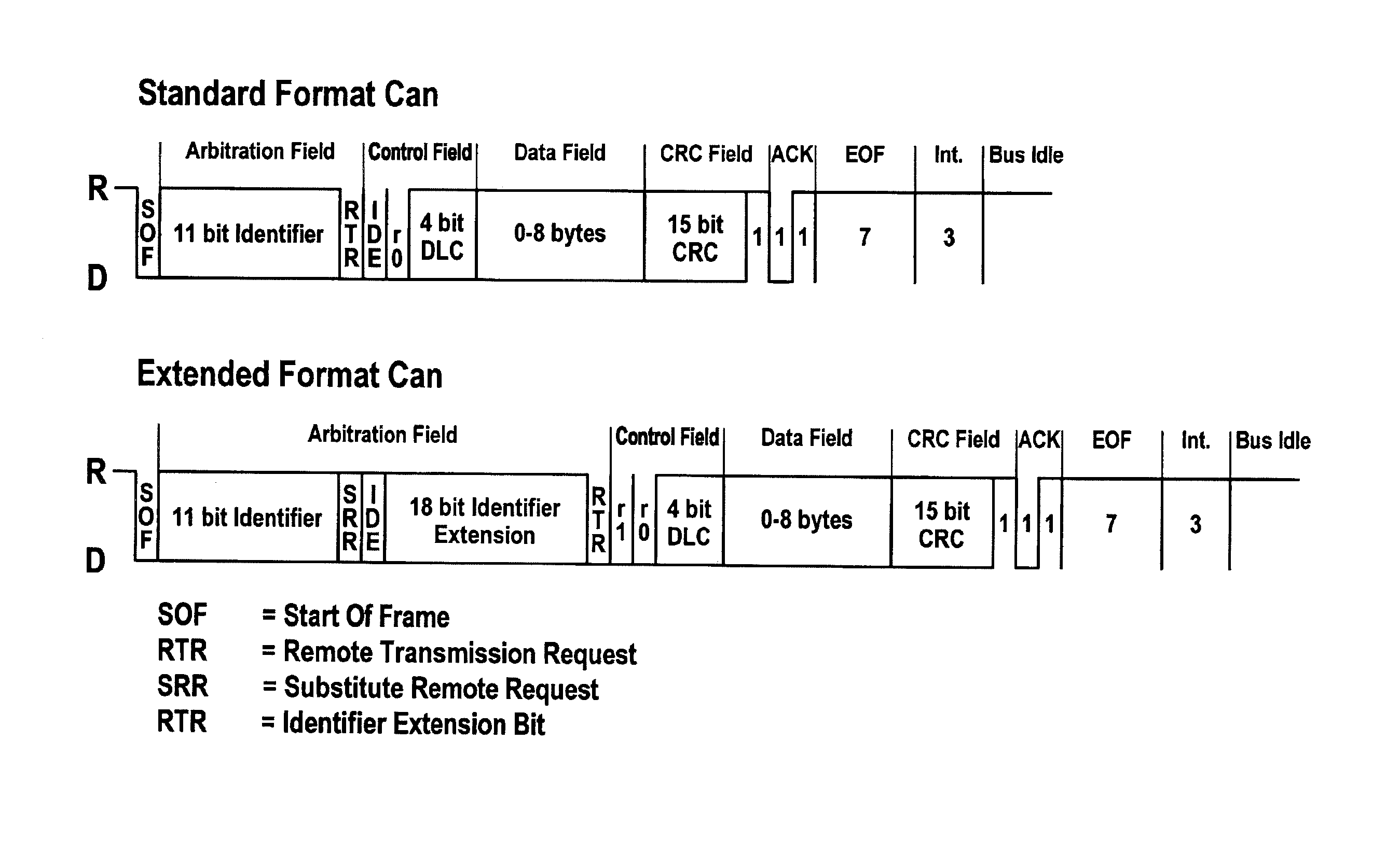
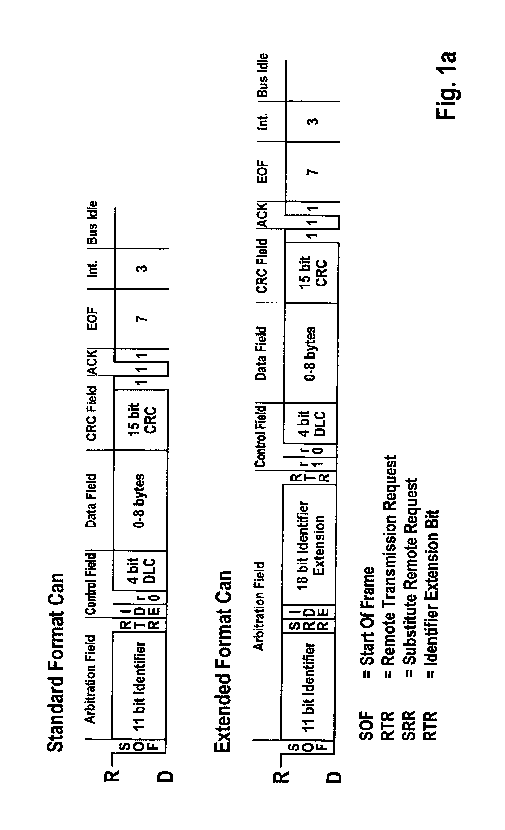
[0031]FIG. 1a illustrates the structure of messages such as those used on a CAN bus for data transmission. The two different formats “standard” and “extended” are illustrated. The method according to the present invention is applicable to both formats in suitable specific embodiments.

[0032]The message begins with a “start of frame” (SOF) bit which signals the start of the message. This bit is followed by a segment which is primarily used for identifying the message, and on the basis of which the users of the bus system decide whether or not they will receive the message. This segment is referred to as the “arbitration field,” and contains the identifier. The segment is followed by a “control field” which contains, among other things, the data length code. The data length code contains information concerning the size of the data field of the message. This field is followed by the actual data field “data field,” which contains the data to be exchanged between the users of the bus syst...


PUM


Abstract

A method is described for checking the correct functioning of a serial data transmission in a bus system having at least two bus users. The bus users are connected to the bus via a bus connection unit and exchange messages via the bus. The sending access to the bus for each message is granted to a bus user via the arbitration process according to CAN standard ISO 11898-1, this bus user becoming the sender for this message. The messages have a logic structure according to the CAN standard, i.e., are composed of a start of frame bit, arbitration field, control field, data field, CRC field, acknowledge field, and end of frame field. The correct functioning of the data transmission is checked during the transmission by comparing a transmission signal, sent to the bus connection unit, to the reception signal (CAN_RX) received by the bus connection unit. The method is characterized in that a transmission signal (CAN_TX_DEL), which is delayed by a delay time (T_DELAY) compared to the transmission signal (CAN_TX), is held in the sender, and the undelayed transmission signal (CAN_TX) or the delayed transmission signal (CAN_TX_DEL) is used for checking the correct functioning of the data transmission, as a function of a switchover.

Description

FIELD OF THE INVENTION[0001]The present invention relates to a method and a device for serial data transmission between at least two users in a bus system.BACKGROUND INFORMATION[0002]The controller area network (CAN) as well as an extension of the CAN, referred to as “time triggered CAN” (TTCAN), also collectively referred to below as the CAN standard, are known from the standards of the ISO 11898-1 through 11898-1 family, for example. The media access control process used in the CAN is based on bitwise arbitration. In the CAN, the bitwise arbitration is carried out based on a leading identifier within the message to be transmitted via the bus.[0003]During the bitwise arbitration, multiple user stations may simultaneously transmit data via the bus system without interfering with the data transmission. At the same time, the user stations may ascertain the logic state (0 or 1) of the bus (reception signal) during transmission of a bit via the bus (transmission signal). For this purpos...

Claims


Application Information

Patent Timeline
Patent Type & Authority Applications(United States)
IPC IPC(8): G06F13/42G06F13/362
CPCG06F13/4282G06F13/362H04L12/4013H04L12/4135H04L2012/40215H04L12/40H04L12/413
Inventor HARTWICH, FLORIANBAILER, FRANZHORST, CHRISTIANMUTTER, ARTHUR
Owner ROBERT BOSCH GMBH
Why Eureka
Try Eureka