Bicycle sprocket
a bicycle and sprocket technology, applied in the field of bicycle sprockets, can solve the problem that the rear end of a conventional bicycle frame only has a limited amount of space, and achieve the effect of effectively strengthening the bicycle sprocket, and effective resisting bending of the bicycle sprock
- Summary
- Abstract
- Description
- Claims
- Application Information
AI Technical Summary
Benefits of technology
Problems solved by technology
Method used
Image
Examples
second embodiment
[0097]Referring now to FIGS. 4 to 8, a rear sprocket assembly 112 (e.g., a multiple sprocket assembly) in accordance with a second embodiment will now be explained. The rear sprocket assembly 112 is basically identical to the rear sprocket assembly 12 in accordance with the first embodiment, except that a plurality of sprockets of the rear sprocket assembly 112 includes a pair of rear sprockets Sa and Sb (e.g., a plurality of bicycle sprockets) detachably coupled to each other, as explained below.
[0098]In view of the similarity between the first and second embodiments, the parts of the second embodiment that are identical to the parts of the first embodiment will be given the same reference numerals as the parts of the first embodiment. Also, parts of this second embodiment that are functionally identical and / or substantially identical to parts of the first embodiment will be given the same reference numerals but with “100” added thereto. In any event, the descriptions of the parts ...
third embodiment
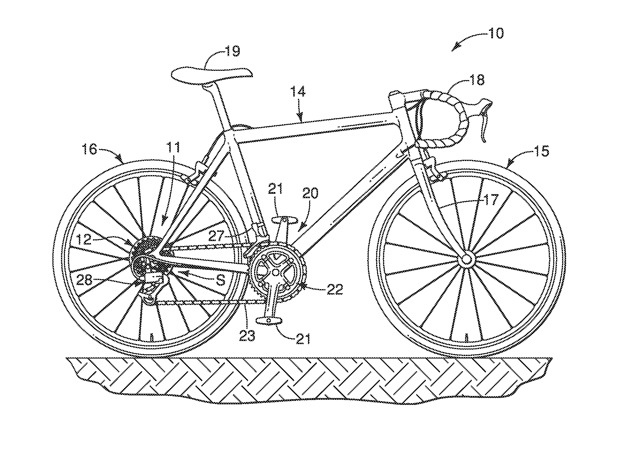
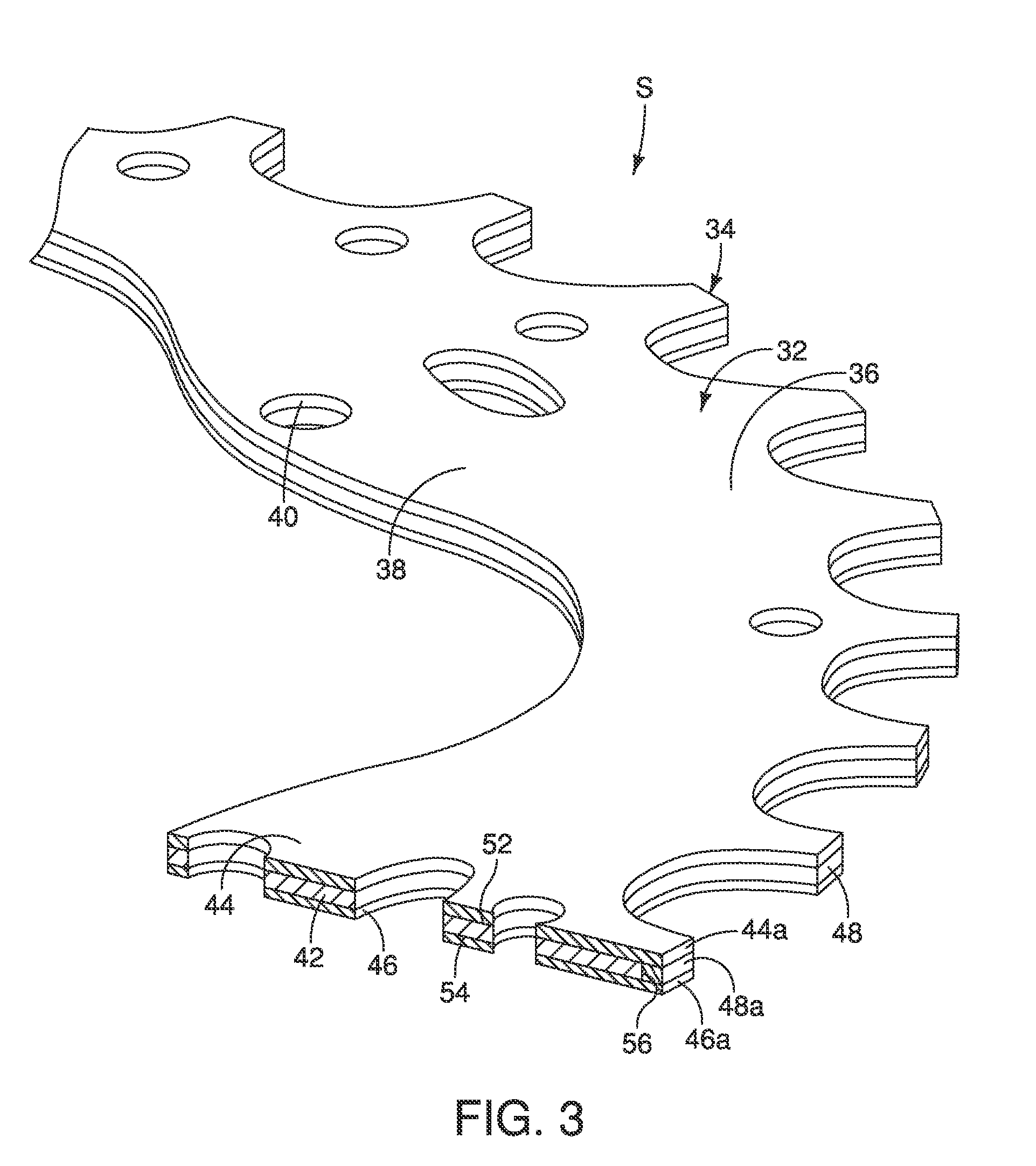
[0118]Referring now to FIGS. 12 to 15, a front sprocket assembly 222 (e.g., a multiple sprocket assembly) in accordance with a third embodiment will now be explained. The front sprocket assembly 222 is basically identical to the front sprocket assembly 22 shown in FIG. 1, except that a sprocket S of the front sprocket assembly 222 includes a multi-layered structure, as explained below.
[0119]In view of the similarity between the first and third embodiments, the parts of the third embodiment that are identical to the parts of the first embodiment will be given the same reference numerals as the parts of the first embodiment. Also, parts of this third embodiment that are functionally identical and / or substantially identical to parts of the first embodiment will be given the same reference numerals but with “200” added thereto. In any event, the descriptions of the parts of the third embodiment that are substantially identical to the parts of the first embodiment may be omitted for the ...
fourth embodiment
[0126]Referring now to FIGS. 16 to 18A, a rear sprocket assembly 312 (e.g., a multiple sprocket assembly) in accordance with a fourth embodiment will now be explained. The rear sprocket assembly 312 is basically identical to the rear sprocket assembly 12 in accordance with the first embodiment, except for a configuration of a sprocket body 332, as explained below.
[0127]In view of the similarity between the first and fourth embodiments, the parts of the fourth embodiment that are identical to the parts of the first embodiment will be given the same reference numerals as the parts of the first embodiment. Also, parts of this fourth embodiment that are functionally identical and / or substantially identical to parts of the first embodiment will be given the same reference numerals but with “300” added thereto. In any event, the descriptions of the parts of the fourth embodiment that are substantially identical to the parts of the first embodiment may be omitted for the sake of brevity. H...
PUM
 Abstract
Description
Claims
Application Information
 - R&D
- Intellectual Property
- Life Sciences
- Materials
- Tech Scout
- Unparalleled Data Quality
- Higher Quality Content
- 60% Fewer Hallucinations
Browse by: Latest US Patents, China's latest patents, Technical Efficacy Thesaurus, Application Domain, Technology Topic, Popular Technical Reports.
© 2025 PatSnap. All rights reserved.Legal|Privacy policy|Modern Slavery Act Transparency Statement|Sitemap|About US| Contact US: help@patsnap.com


