
Method And Device For Determining An Operating Parameter Of A Fluid Insulated Electrical Apparatus

a technology of fluid insulated electrical apparatus and operating parameter, which is applied in the direction of instruments, air-break switches, and testing dielectric strength, etc., can solve the problems of not determining the dielectric breakdown strength e/sub>bd or an e/sub>bd, and the dielectric gas cannot allow the passage of electrical current, etc., to achieve suitable mixing ratio, reduce the gaseous amount of the condensed component, and improve the effect of insulation performan

Active Publication Date: 2014-10-16
HITACHI ENERGY SWITZERLAND AG
View PDF4 Cites 2 Cited by
  • Summary
  • Abstract
  • Description
  • Claims
  • Application Information

AI Technical Summary

Benefits of technology

The patent describes a method for measuring different characteristics of an insulation fluid in a fluid-insulated electrical apparatus. This allows for easier determination of the concentrations of different components in the fluid. The method involves using sensors to measure these characteristics, such as pressure, temperature, and density. The control and analysis unit can also use predefined values to determine critical field strengths and synergy parameters for different combinations of components. The technical effect of this patent is to improve the safety and reliability of fluid-insulated electrical apparatuses by monitoring the condition of the insulation fluid in real-time.

Problems solved by technology

In other words, the insulation gas does not allow the passage of electrical current from the electrically active part to the compartment.
Because the dielectric breakdown strength Ebd of such multi-component fluid mixtures depends, e.g., on the concentration ratio of the mixture components, its derivation becomes more complicated than for single component insulation fluids, however.
The disclosed methods and devices have the disadvantage, however, that they do not determine the dielectric breakdown strength Ebd or an Ebd-dependent operating parameter, which is a prominent parameter relevant for assessment of an operating state of the gas-insulated electrical apparatus.

Method used


Image

  • Method And Device For Determining An Operating Parameter Of A Fluid Insulated Electrical Apparatus
  • Method And Device For Determining An Operating Parameter Of A Fluid Insulated Electrical Apparatus
  • Method And Device For Determining An Operating Parameter Of A Fluid Insulated Electrical Apparatus

Examples


Embodiment Construction

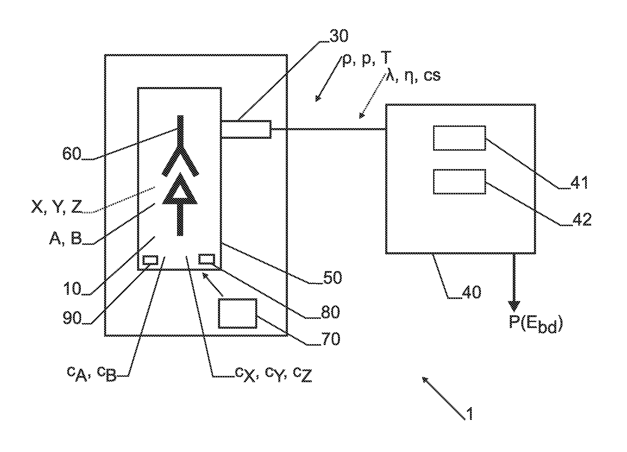
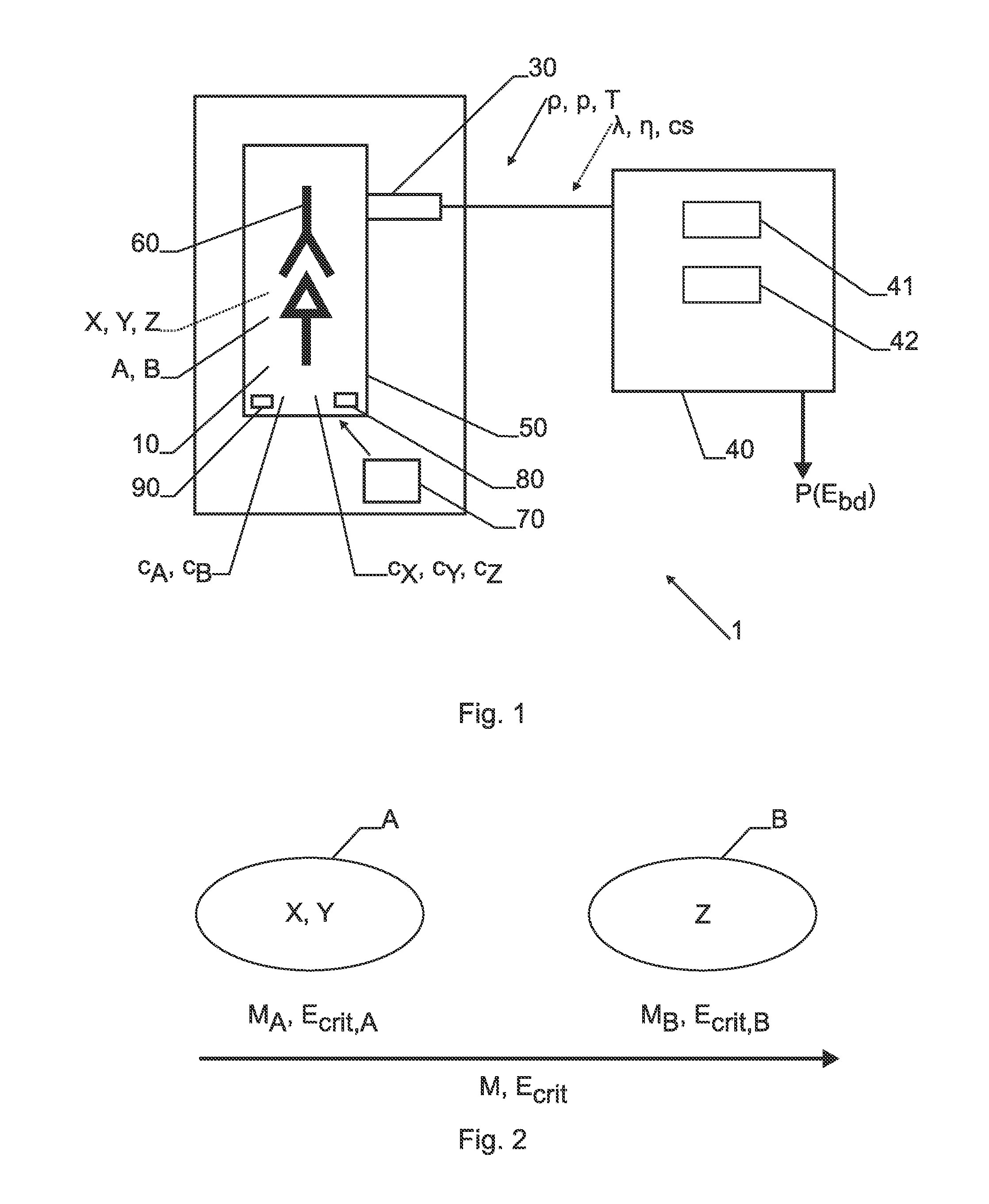
[0101]FIG. 1 shows a schematic of a fluid-insulated electrical apparatus 1, i.e. here a gas insulated switch 1. An electrically active part 60 of the fluid-insulated apparatus 1 is arranged in a gas-tight compartment 50 which encloses an insulation fluid 10 for preventing the passage of electrical current from the electrically active part 60 to the compartment 50. The insulation fluid 10 is an insulation gas 10 comprising the component X which is nitrogen N2 with a partial pressure pX=p(N2)=5.29 bar, the component Y which is oxygen O2 with a partial pressure pY=p(O2)=1.41 bar and the component Z which is “perfluoroketone C5” (see definition below) with a partial pressure pZ=p(C5)=0.3 bar at a temperature of 20° C. The total filling pressure p=pX+pY+pZ at filling time is p=pX+pY+pZ=7 bar, the total volume of the gas-tight compartment 50 (filling volume of the insulation gas 10) is V=2 m3. As an option, additionally or as replacement for component Z, a component “perfluoroketone C6” w...


PUM


Abstract

A method for deriving at least one operating parameter of a fluid-insulated electrical apparatus, in particular of gas-insulated switchgear. The operating parameter is dependent on a dielectric breakdown strength of an insulation fluid of the electrical apparatus. The insulation fluid includes at least three components that are assigned to at least a first and a second component group such that at least one component group comprises at least two components. The component groups differ in their weighted average values of the molecular masses of the components in the respective component groups. At least one quantity which is indicative of the concentration of the first component group and of the concentration of the second component group is determined from the insulation fluid, e.g. by measuring one or more measurement variables with one or more sensors. The operating parameter is then derived using the at least one quantity.

Description

FIELD OF THE INVENTION[0001]The present invention relates to methods for deriving at least one operating parameter P of a fluid-insulated electrical apparatus and for operating such an electrical apparatus. Furthermore, it relates to such an electrical apparatus having an analysis and control unit implementing such a method.BACKGROUND OF THE INVENTION[0002]Dielectric insulation media in liquid and / or gaseous states (i.e. fluids) are widely applied to insulate an electrically active part in a variety of electrical apparatuses, such as switchgears or transformers. For example, the electrically active part in medium or high voltage metal-encapsulated switchgears is arranged in a gas-tight compartment which encloses an insulation gas with a pressure of several bars, which electrically separates the compartment of the apparatus from the electrically active part. In other words, the insulation gas does not allow the passage of electrical current from the electrically active part to the co...

Claims


Application Information

Patent Timeline
Patent Type & Authority Applications(United States)
IPC IPC(8): G01R31/12G01R31/06G01R31/327
CPCH01H33/563H01H2033/566G01R31/1281G01R31/3275G01R31/06
Inventor KRAMER, AXELPAUL, THOMAS ALFREDMAHDIZADEH, NAVIDRANJAN, NITESH
Owner HITACHI ENERGY SWITZERLAND AG
Learn More