
Apparatus and method for generating nitric oxide in controlled and accurate amounts

a technology of nitric oxide and controlled amounts, applied in the direction of nitric oxide, disinfection, energy-based chemical/physical/physicochemical processes, etc., can solve the problems of large volume of compressed nitric oxide gas cylinders, high labor intensity, and high labor intensity, so as to achieve effective removal of adulterants and accurate representation of the remaining capacity. , the effect of high level of adulterants

Active Publication Date: 2014-09-11
NITRICGEN
View PDF1 Cites 59 Cited by
  • Summary
  • Abstract
  • Description
  • Claims
  • Application Information

AI Technical Summary

Benefits of technology

The invention provides an improved apparatus and method for generating nitric oxide using a gas plasma produced by electric discharges across two electrodes. The invention solves previous disadvantages by controlling both the pulse frequency and duration of electric pulse discharges, resulting in accurate nitric oxide generation at a wide range of gas flow rates and concentrations. The apparatus design reduces electrode wear and simplifies the setup and use of the apparatus. The filter memory can be programmed with dose settings and alarms for different biological systems, allowing for tight or loose dosing specifications. The invention provides a versatile nitric oxide generating apparatus with low levels of impurities.

Problems solved by technology

One issue that has to be taken into account when considering a method of nitric oxide delivery is that of nitrogen dioxide (NO2) generation.
Nitric oxide, when in the presence of oxygen, reacts to form nitrogen dioxide, which is am irritant to biological systems.
The main problem with this approach is that the cylinders of compressed nitric oxide gas are large and heavy and are logistically difficult and expensive to ship from the centralized location to the site of application.
It is however, more difficult to accurately and controllably produce the required amounts of nitric oxide with the required purity.
The current from the capacitor is not controlled once break down voltage has occurred, and this results in an arc discharge which is quick and intense with a high current and high gas temperatures.
There are a number of problems with this type of system which include: electric arc discharges cause high current at high temperatures which cause vaporization of the electrode material which leads to excessive wear of the electrodes.
Electrode wear is a function of the intensity of the discharge across the electrodes, which translates into the higher the current the higher the electrode wear.
The high temperature can also result in higher levels of nitrogen dioxide being formed, which is not desired in a number of biological applications.
In addition, due to the electrode wear, the amount of nitric oxide generated in this system is not accurately predictable over periods of time and it requires a nitric oxide gas analyzer to ensure the expected amount of nitric oxide is being generated accurately.
A gas analyzer adds expense, bulk and requires the user to calibrate it prior to use, which makes it undesirable for an optimum nitric oxide generation system.
However the soda lime filter material disclosed has a finite life, and if it is not changed when the life of the filter material is exhausted, the system would allow the nitrogen dioxide to be delivered to the biological system, and this could result in harm to the biological system.
The disadvantages of this approach are that there is a limited range of current that allows a glow discharge to be formed, and once formed the glow discharge needs to be continuously maintained.
This limits the controllable range of the nitric oxide that can be produced.
However, this means both the gas flow rate and nitric oxide concentration cannot be controlled independently.
If lower concentrations of nitric oxide at low gas flow rates are required, then a large portion of the nitric oxide generated is discarded resulting in low efficiency of operation and an additional apparatus associated with safely disposing of the unused nitric oxide gas flow.
The disadvantage of this apparatus is that it requires extra electrical power to heat the gas to 400° C. to 800° C. and then requires the gas to be actively cooled after the reactor chamber before it can be used clinically.
This significantly increases the power and complexity of the apparatus.
It also has the same problem as EP 0719159, in that it provides a limited controllable range of nitric oxide being produced, and also relies on gas dilution to produce the desired nitric oxide concentration.
Therefore it has the same limitation as described in EP 0719159 in that in some applications, it will result in unwanted nitric oxide gas flow that will need to be discarded resulting in inefficient operation and the need for additional apparatus for the safe disposal of the unused nitric oxide.
This drop in nitric oxide concentration is due to the gas mixing with ambient air, and means a large part of the nitric oxide generated never gets to the intended biological target.
The apparatus disclosed has the same problems as previous art in that the amount of nitric oxide generated is not well controlled and relies on wasteful dilution of the nitric oxide prior to delivery to the biological target.
1) The prior art does not disclose apparatus that can control the amount of nitric oxide over a wide range of gas flows and nitric oxide concentrations so that the device can be used for multiple distinct dosing regimens depending on the target application.
2) The prior art does not disclose apparatus that allows for a wide range of nitric oxide outputs without requiring additional gas flow dilution. This results in excess nitric oxide generation that has to be safely disposed of, causing extra cost and complexity.
3) The prior art that uses high voltage electric arc discharges to generate nitric oxide has high electrode wear due to electrode vaporization caused by the intense electric arc discharges.
4) The prior art that uses corona discharges require high reaction chamber temperatures to be maintained that needs additional power, and then require gas cooling systems to bring the gas flow back down to acceptable temperature levels prior to administration, thus adding to the cost, complexity and poor efficiency of the system.
5) None of the prior art provides a simple way of monitoring the correct functioning of the arc discharge so the amount of nitric oxide generated can be accurately predicted.
6) None of the prior art discloses a consumable filter for removing NO2 and other adulterants from the nitric oxide gas flow that when consumed, can provide the nitric oxide apparatus with a means of alerting the user that it needs to be replaced.

Method used


Image

  • Apparatus and method for generating nitric oxide in controlled and accurate amounts
  • Apparatus and method for generating nitric oxide in controlled and accurate amounts
  • Apparatus and method for generating nitric oxide in controlled and accurate amounts

Examples


Embodiment Construction

[0065]In the following detailed description the term “air” will be used to generally describe the oxygen and nitrogen gas mixture used in reactor chamber to generate nitric oxide, but also other gas mixtures containing oxygen and nitrogen that may have been produced from alternative gas sources such gas cylinders that are commonly used in anesthesia machines and may include alternate concentrations.

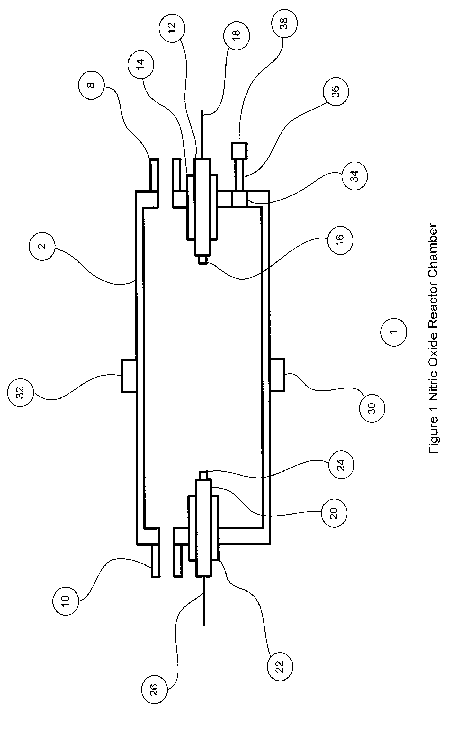
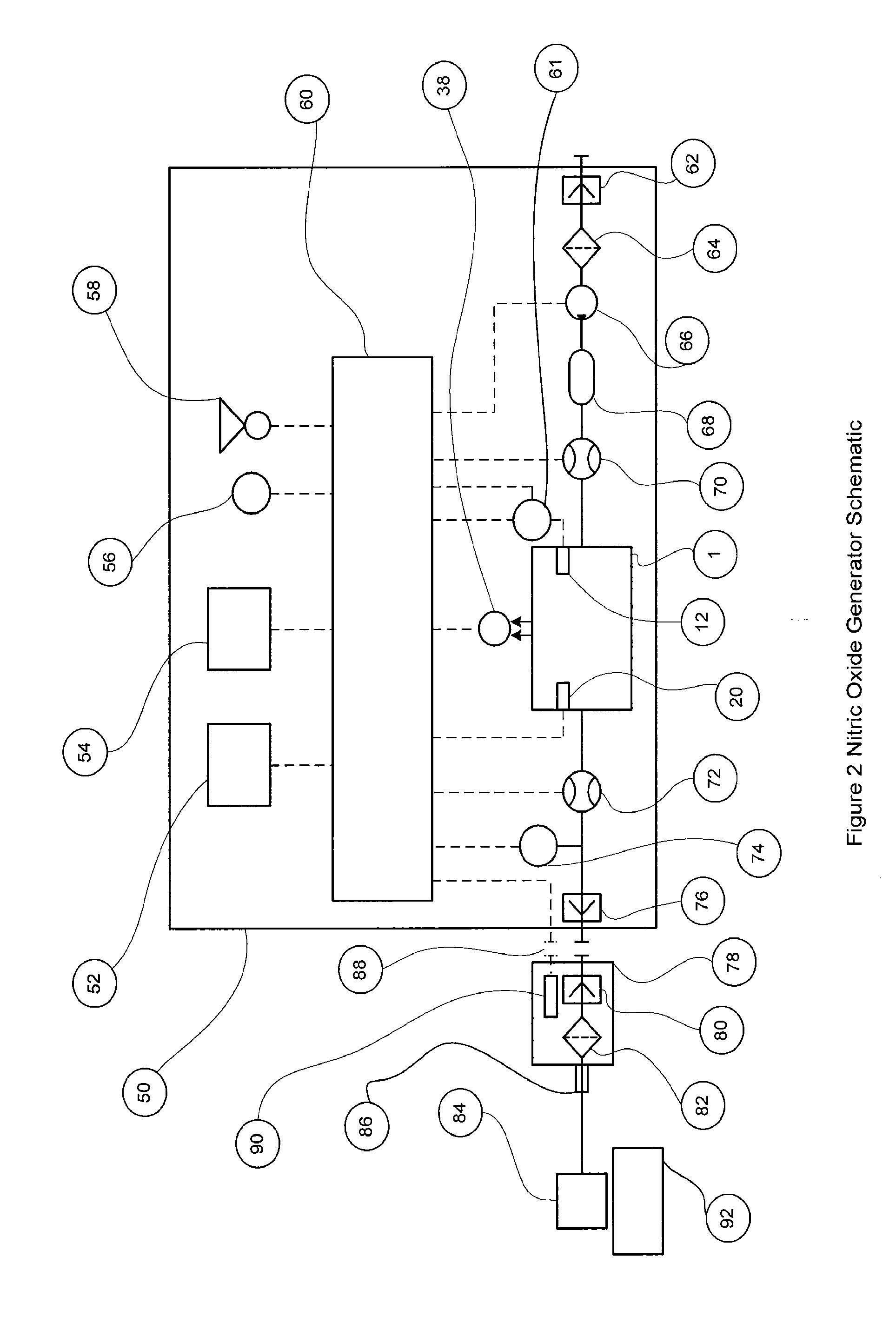
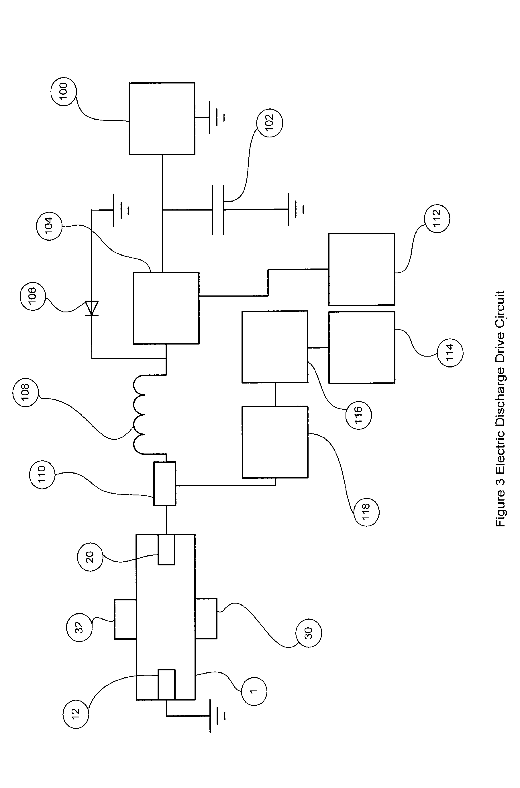
[0066]FIG. 1 shows the nitric oxide reactor chamber 1 with a reactor housing 2 which has a reactor gas inlet port 8 and a first electrode 12 on one side and a reactor gas outlet port 10 and a second electrode 20 on the other side. The electrodes can be insulated with non-electrically conducting material 14 and 22 if the chamber housing is made of a material that is electrically conducting. The electrodes can have an electrode tip 16 and 24 made of a material that is resistant to high temperatures and is less susceptible to vaporization, oxidization and wear. Materials for the electrode ti...


PUM

PropertyMeasurementUnit
Timeaaaaaaaaaa
Timeaaaaaaaaaa
Frequencyaaaaaaaaaa

Abstract

A nitric oxide generator generates nitric oxide from a mixture of nitrogen and oxygen such as air treated by a pulsating electrical discharge. The desired concentration of nitric oxide is obtained by controlling at least one of a frequency of the pulsating electrical discharge and duration of each electrical discharge pulse.

Description

CROSS REFERENCE TO RELATED APPLICATION[0001]This application claims the benefit of U.S. provisional application 61 / 542,400 filed Oct. 3, 2011 and hereby incorporated by reference.STATEMENT REGARDING FEDERALLY SPONSORED RESEARCH OR DEVELOPMENT[0002]N / ABACKGROUND OF THE INVENTION[0003]This invention discloses a method and apparatus for the production of nitric oxide (NO) in controlled and accurate amounts, with low levels of impurities by controlling electric discharges between two electrodes in an oxygen nitrogen gas mixture.[0004]Nitric oxide is known to have many applications in biological systems of both plants and animals.[0005]In plants it is known that modifying the local atmospheric concentration of nitric oxide can stimulate a number of beneficial effects including, improved growth (U.S. Pat. No. 6,242,384), reduction in seed dormancy (Bethke, 2006 and Sarath, 2006), protection from fungal infections and disease (Lazar, 2008 and Hong, 2007) and preservation of cut flowers and...

Claims


Application Information

Patent Timeline
IPC IPC(8): B01J19/08C01B21/20B01D53/02A61K33/00B01D46/00
CPCB01J19/088A61K33/00C01B21/203B01D46/0084B01D53/02B01D46/00B01J2219/0809B01J2219/0815B01J2219/0826B01J2219/0852B01J2219/0869B01J2219/0875B01J2219/0883B01J2219/0894C01B21/32H05H1/46B01J20/041B01J20/08B01J20/103B01J20/20B01J20/22B01J20/28047B01J2219/0801H04L9/30H05H1/50
Inventor MONTGOMERY, FREDERICK JOHNCASPER, CORYBATHE, DUNCAN P.L.GRIBB, TYE
Owner NITRICGEN
Learn More