
Valve assembly intended for use together with a pallet container and a liner

Inactive Publication Date: 2014-08-21
SCHOELLER ARCA SYST
View PDF5 Cites 12 Cited by
  • Summary
  • Abstract
  • Description
  • Claims
  • Application Information

AI Technical Summary

Benefits of technology

The present invention improves the manufacturing process and enhances the mechanical properties of a valve. The lower and upper guide members are snap-fitted over the tube-shaped body for easy disassembly without special tools for material recovery. The tube-shaped body is provided with an annular internal groove matching the closed position of the valve, reducing the risk of leakage, unintentional opening of the valve, and providing tactile confirmation when closing and opening a valve. In an alternative embodiment, the support member can also have an annular internal groove matching the closed position of the valve.

Problems solved by technology

In many cases, the valve is designed in such a way that material recovery is virtually impossible.
This will put some demands on the material used for making the components of the valve.

Method used


Image

  • Valve assembly intended for use together with a pallet container and a liner
  • Valve assembly intended for use together with a pallet container and a liner
  • Valve assembly intended for use together with a pallet container and a liner

Examples


first embodiment

[0025]FIG. 1 show, in perspective view, part of a collapsible container 1. FIG. 1 show a valve assembly 2 in a valve opening 1E according to the invention.

second embodiment

[0026]FIG. 2 show, in perspective view, part of a collapsible container 1. FIG. 2 show a valve assembly 2 in a valve opening 1E according to the invention.

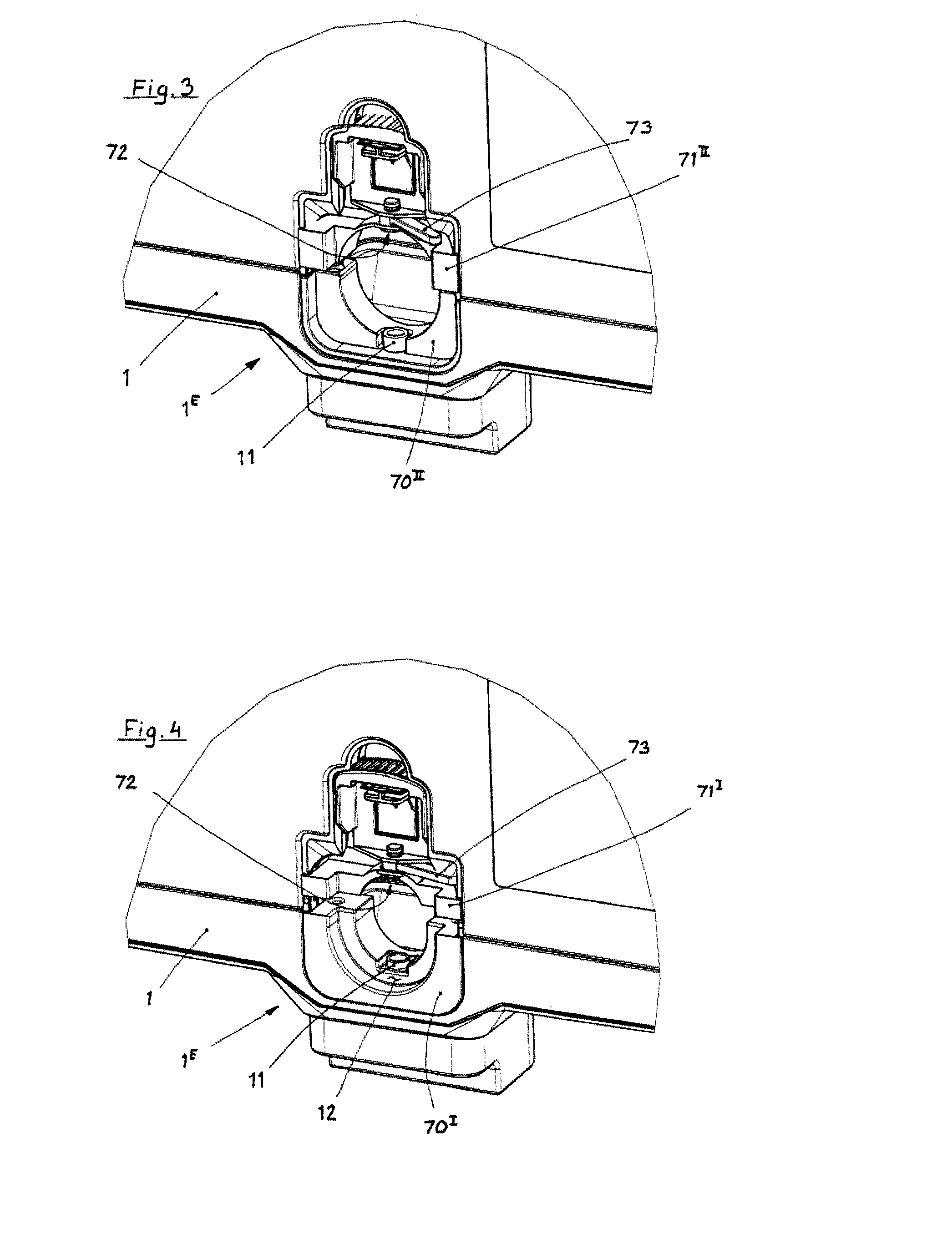
[0027]FIG. 3 show, in perspective view, the embodiment of FIG. 1 before insertion of liner and valve according to the invention.

[0028]FIG. 4 show, in perspective view, the embodiment of FIG. 2 before insertion of liner and valve according to the invention.

[0029]FIG. 5a show, in perspective view as seen from below, an embodiment of a valve assembly 3 according to the invention.

[0030]FIG. 5b show, in perspective view as seen from above, an embodiment of a valve assembly 3 according to the invention.

[0031]FIG. 5c show, in perspective view and in exploded view, an embodiment of a valve assembly 3 according to the invention.

[0032]FIG. 6 show, in perspective view, a valve size adapter 70I from FIG. 4.

[0033]FIG. 7 show, in perspective view, a matching upper member 71I from FIG. 4.

[0034]FIG. 8 show, in perspective and exploded view an alt...


PUM


Abstract

A valve assembly (2) intended for use together with a pallet container (1) and a liner. The valve assembly (2) comprises a support member (6). The support member (6) is provided with a guiding hole (63) intended to interact with a lower valve guide member (11).

Description

BACKGROUND OF THE INVENTION[0001]1. Field of the Invention[0002]The present invention relates to a novel and improved valve assembly for hulk containers with liner and a container thereto.[0003]2. Description of Related Prior Art[0004]Products made of thermoplastic materials can be manufactured by a number of different manufacturing procedures. The most commonly used methods are however, injection moulding, vacuum forming, blow moulding and press moulding.[0005]Valves of butterfly and of ball type have been known for some time and they can be manufactured from thermoplastic material. Here injection moulding and press moulding are the most suited manufacturing methods in order to achieve the desired precision. Butterfly valves and ball valves made of thermoplastic materials are mostly used in low-pressure systems. Butterfly valves are often used in ventilation appliances where absolute closing is not necessary. It is also possible to use the valves for fluid media. It will of course ...

Claims


Application Information

Patent Timeline
IPC IPC(8): F16K1/226
CPCF16K1/226B65D47/20B65D77/061B65D77/22B65D77/067F16K1/22F16K27/00
Inventor KNUTSSON, ANDERS
Owner SCHOELLER ARCA SYST
Learn More