Radiographic imaging apparatus, radiographic imaging system, and radiographic imaging method

Active Publication Date: 2014-08-07
FUJIFILM CORP
View PDF9 Cites 24 Cited by
  • Summary
  • Abstract
  • Description
  • Claims
  • Application Information

AI Technical Summary

Benefits of technology

The present invention aims to solve the problem of errors between the set dosing amount and the actual dosing amount in X-ray sources. By adjusting the gain, the invention ensures that even when the dosing amount is small, a good quality radiographic image can be obtained without overexposure or underexposure.

Problems solved by technology

However, a problem arises in that, to further reduce overflow and underflow, the method described in JP2005-143802A is not sufficient.
However, if the gain is adjusted based on the reference pixel in the bypass region, underflow tends to occur in the subject region which is an observation target in the X-ray image.
In this case, the gain is adjusted to a high value, but the gain becomes excessively high in a soft tissue such as a lung where the X-ray transmittance is high compared with the bone portion, and thus overflow occurs.
Compared with the case where the dosing amount is large, in a case where the dosing amount is small, it is difficult to obtain an X-ray image with good image quality unless the gain adjustment is appropriately performed.
Further, if radiography ends in failure due to overflow or underflow, re-radiography is necessary.
However, it is apparent that this re-radiography increases the amount of radiation exposure.

Method used


Image

  • Radiographic imaging apparatus, radiographic imaging system, and radiographic imaging method
  • Radiographic imaging apparatus, radiographic imaging system, and radiographic imaging method
  • Radiographic imaging apparatus, radiographic imaging system, and radiographic imaging method

Examples


first embodiment

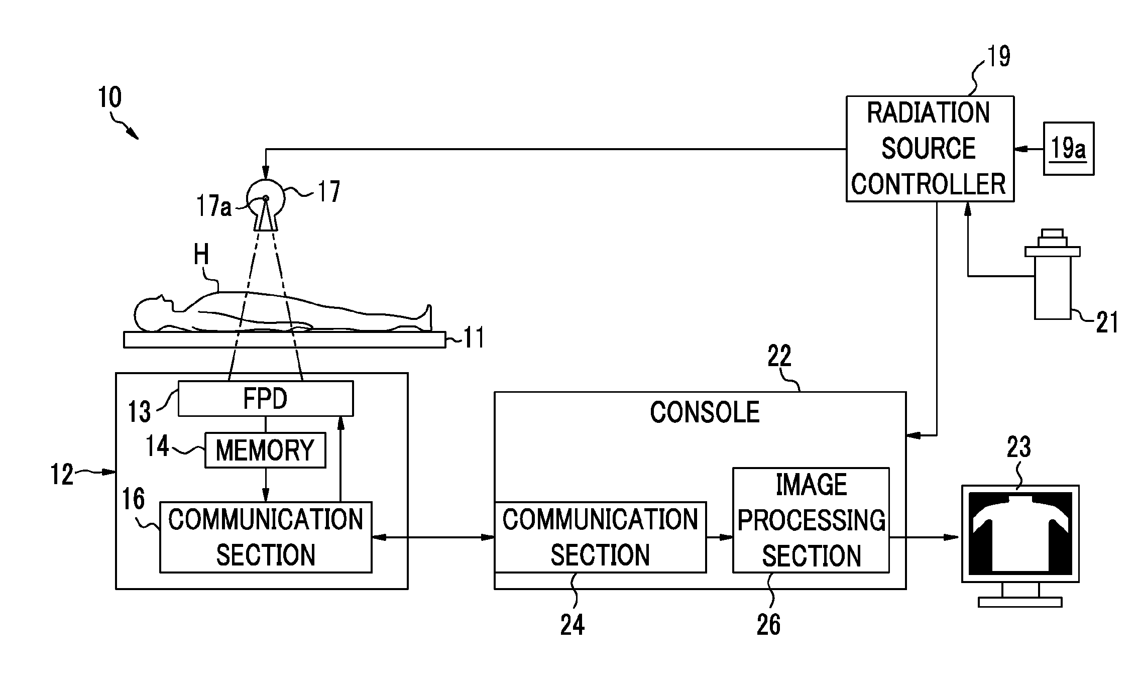
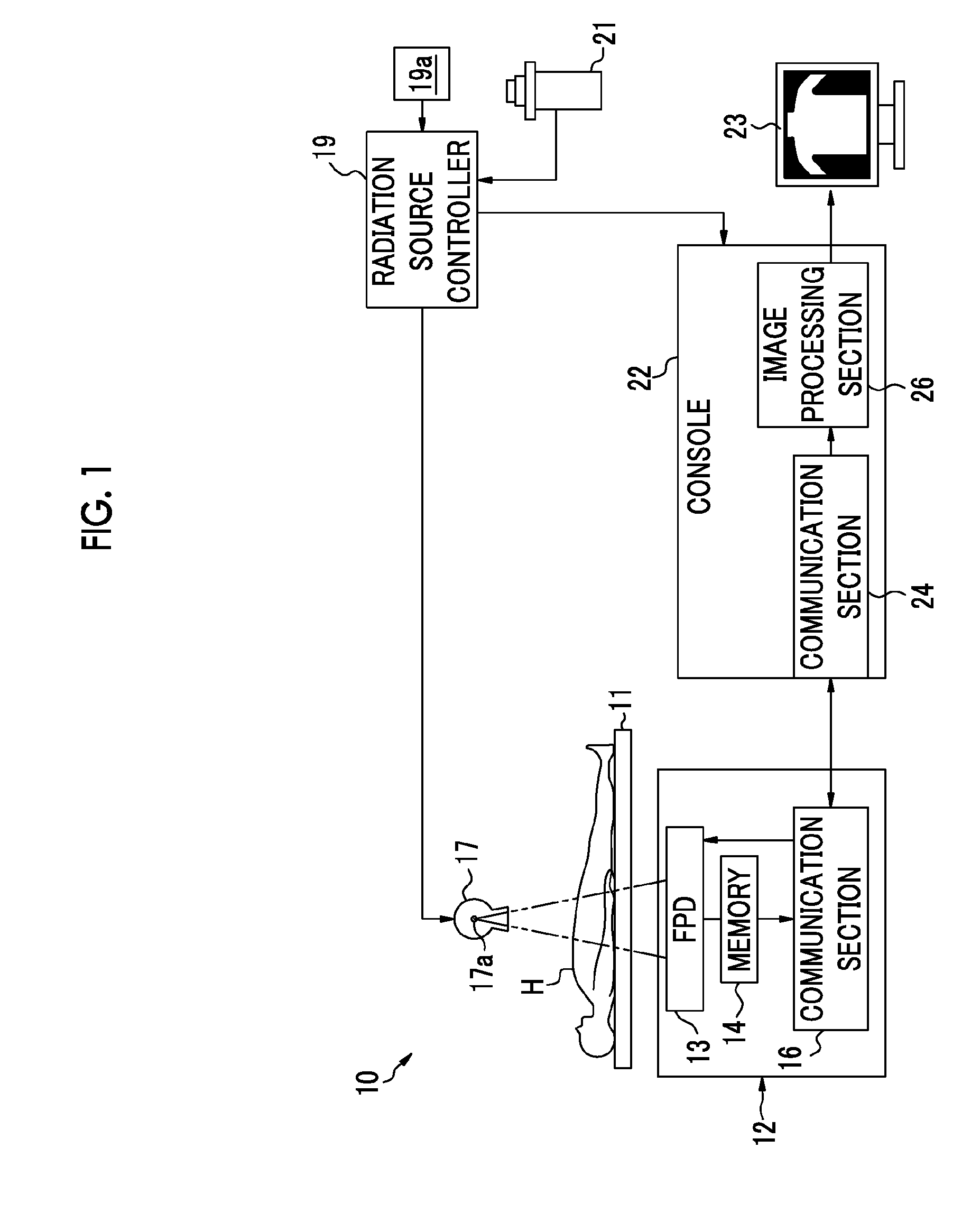
[0067]As shown in FIG. 1, an X-ray imaging system 10 includes an imaging stage 11, an electronic cassette (radiographic image detection device) 12, an X-ray source 17, a radiation source controller 19, a console 22, a monitor 23, and the like. The X-ray source 17 and the radiation source controller 19 constitute an X-ray generator. The electronic cassette 12, the console 22, and the monitor 23 constitute an X-ray imaging apparatus (radiographic imaging apparatus).

[0068]A subject H is placed on the imaging stage 11, and the electronic cassette 12 is set on the imaging stage 11 or between the imaging stage 11 and the subject H such that X-rays transmitted though the subject H are incident thereto.

[0069]The electronic cassette 12 is detachably provided on the imaging stage 11, and is a portable type which is usable even when the imaging stage 11 is not used, and is provided with an FPD 13, various circuits that control operations of the FPD 13, a memory 14, a communication section 16, ...

second embodiment

[0119]In the description of the above-mentioned first embodiment, the following example was given: by performing the rereading while changing the gain of the amplifier 72 until it is possible to obtain the X-ray image appropriate for observation of the subject H, only the X-ray image, which is finally read with an appropriate gain, is transmitted to the console 22. However, as described later in the second embodiment, by transmitting a plurality of the read X-ray images is transmitted to the console 22 while changing the gain of the amplifier 72 and by synthesizing the images, the X-ray image appropriate for observation of the subject H may be obtained. The second embodiment is the same as the first embodiment except the difference that a plurality of the X-ray images is synthesized. Accordingly, hereinafter, description will be given focusing on the difference. In addition, the common elements are represented by the same reference numerals and signs, and description thereof will be...

third embodiment

[0137]As shown in FIG. 12, each pixel PX of the FPD 13 is formed of a photodiode PD and transistors M1 to M3, and performs an accumulation operation, a reading operation, and a reset operation, in accordance with driving states of the respective transistors M1 to M3. The accumulation operation is an operation that accumulates the signal electric charge which is generated by photoelectric conversion, and the reading operation is an operation that outputs a voltage signal corresponding to the amount of the accumulated signal electric charge. The reset operation is an operation that drains the accumulated signal electric charge.

[0138]The photodiode PD is an element that generates a signal electric charge corresponding to the amount of light incident from the scintillator 41 through photoelectric conversion, and is connected to a gate electrode of an amplification transistor M1 and a source electrode of a reset transistor M3. In the case where the signal electric charge is accumulated a...


PUM


Abstract

There are provided the following components: an FPD that has a plurality of pixels, in which signal electric charges corresponding to amounts of X-rays incident are accumulated, and that is capable of nondestructively reading data which indicates the X-ray image; an amplifier that amplifies a signal sent from the FPD and has a variable gain; an evaluation value calculation section that obtains an evaluation value for evaluating the X-ray image; and a gain adjustment section that calculates a new gain of the amplifier used at the time of rereading. The gain of the amplifier is changed to a value of a new gain which is calculated by the gain adjustment section, and the X-ray image is reread.

Description

CROSS REFERENCE TO RELATED APPLICATIONS[0001]This application is a Continuation of PCT International Application No. PCT / JP2012 / 077268 filed on Oct. 22, 2012, which claims priority under 35 U.S.C §119(a) to Patent Application No. 2011-240514 filed in Japan on Nov. 1, 2011 and Patent Application No. 2011-240515 filed in Japan on Nov. 1, 2011, all of which are hereby expressly incorporated by reference into the present application.BACKGROUND OF THE INVENTION[0002]1. Field of the Invention[0003]The present invention relates to a radiographic imaging apparatus, a radiographic imaging system, and a radiographic imaging method for radiographing a radiographic image of a subject by using a radiographic image detector.[0004]2. Description of the Related Art[0005]Recently, in the field of radiography, for example, X-ray imaging, instead of an X-ray film or an imaging plate (IP), X-ray image detection devices (hereinafter referred to as electronic cassettes) using a flat panel detector (herei...

Claims


Application Information

Patent Timeline
IPC IPC(8): G03B42/02
CPCG03B42/02G03B42/04H04N5/32A61B6/4233A61B6/4283H04N23/71H04N23/76A61B6/5258A61B6/582G06T11/005G01T1/247G01T1/246G06F18/22H04N25/46H04N25/62H04N25/65H04N25/75G06T5/70
Inventor NISHINO, NAOYUKIIWAKIRI, NAOTOKOBAYASHI, TAKEYASU
Owner FUJIFILM CORP
Why Eureka
Try Eureka