
In-line arrangement for measuring polarization extinction ratio

a technology of polarization extinction and inline arrangement, which is applied in the direction of optical fiber with polarisation, optical radiation measurement, instruments, etc., can solve the problems of reducing not always convenient, and not always possible, so as to increase the accuracy of the resultant per

Inactive Publication Date: 2014-08-07
OFS FITEL LLC
View PDF3 Cites 8 Cited by
  • Summary
  • Abstract
  • Description
  • Claims
  • Application Information

AI Technical Summary

Benefits of technology

The invention proposes an in-line monitoring device that can measure the polarization extinction ratio of an optical signal without disconnecting the optical fiber or other waveguiding means of the system. This allows for continuous monitoring of the signal over time, with adjustments to polarization alignment between components being made as needed to maintain the desired ratio. The device is an in-line device, positioned directly along the signal path of the system, and provides an instantaneous measure of the optical signal's polarization extinction ratio without disrupting the operation of the system.

Problems solved by technology

Additionally, the polarization maintaining properties of the optical fiber may degrade over time due to environmental effects (e.g., heat, stress, tight bends, etc.).
This is not always convenient, particularly after a system has been deployed in the field and it is desired to obtain an updated measurement of the signal's PER.
Some of these prior art techniques require that a section of optical fiber be stretched or heated; again, this is not always possible.
Additionally, since a number of separate measurements must be performed over time to calculate the PER, it is not easy to obtain updated measurements—a significant limitation of the prior art.

Method used


Image

  • In-line arrangement for measuring polarization extinction ratio
  • In-line arrangement for measuring polarization extinction ratio
  • In-line arrangement for measuring polarization extinction ratio

Examples


Embodiment Construction

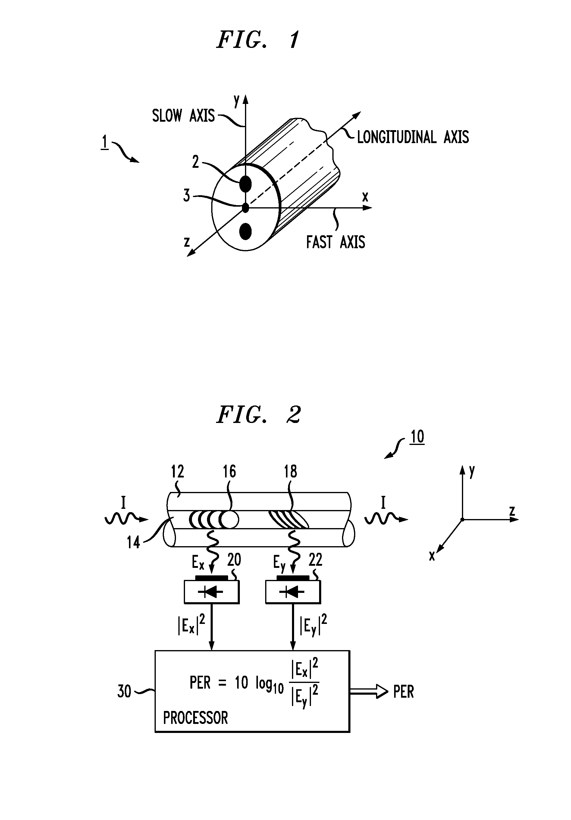
[0029]FIG. 2 illustrates an arrangement formed in accordance with the present invention for providing in-line measurement and monitoring of the polarization extinction ratio (PER) of a propagating optical signal. The term “in-line” is taken to mean that the monitor is preferably disposed along the signal path of a given optical system and does not require any disruption of the system's operation or removal of components (such as, for example, an optical fiber used as the transmission medium in the system) in order to perform the PER measurement.

[0030]The exemplary PER monitor 10 is shown as comprising a section of optical fiber 12 that includes a core region 14, with an optical signal I coupled into core region 14 and propagating in the manner shown in FIG. 2. As shown in FIG. 2, optical signal I propagates along the longitudinal axis of fiber 12 (denoted as the z-axis), with the x- and y-axes defined as being transverse to optical fiber 12.

[0031]Also included in monitor 10 is a pai...


PUM


Abstract

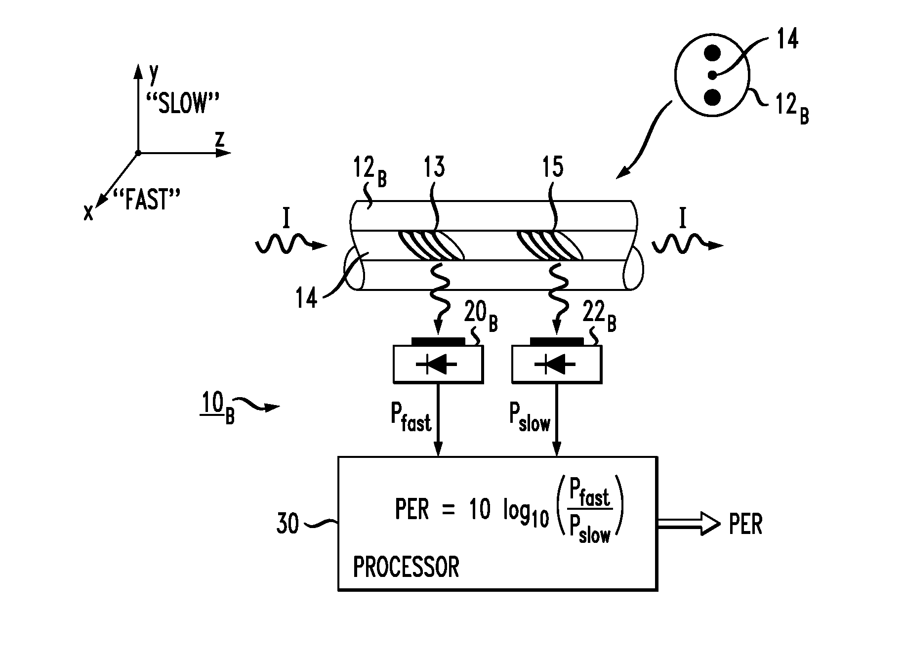
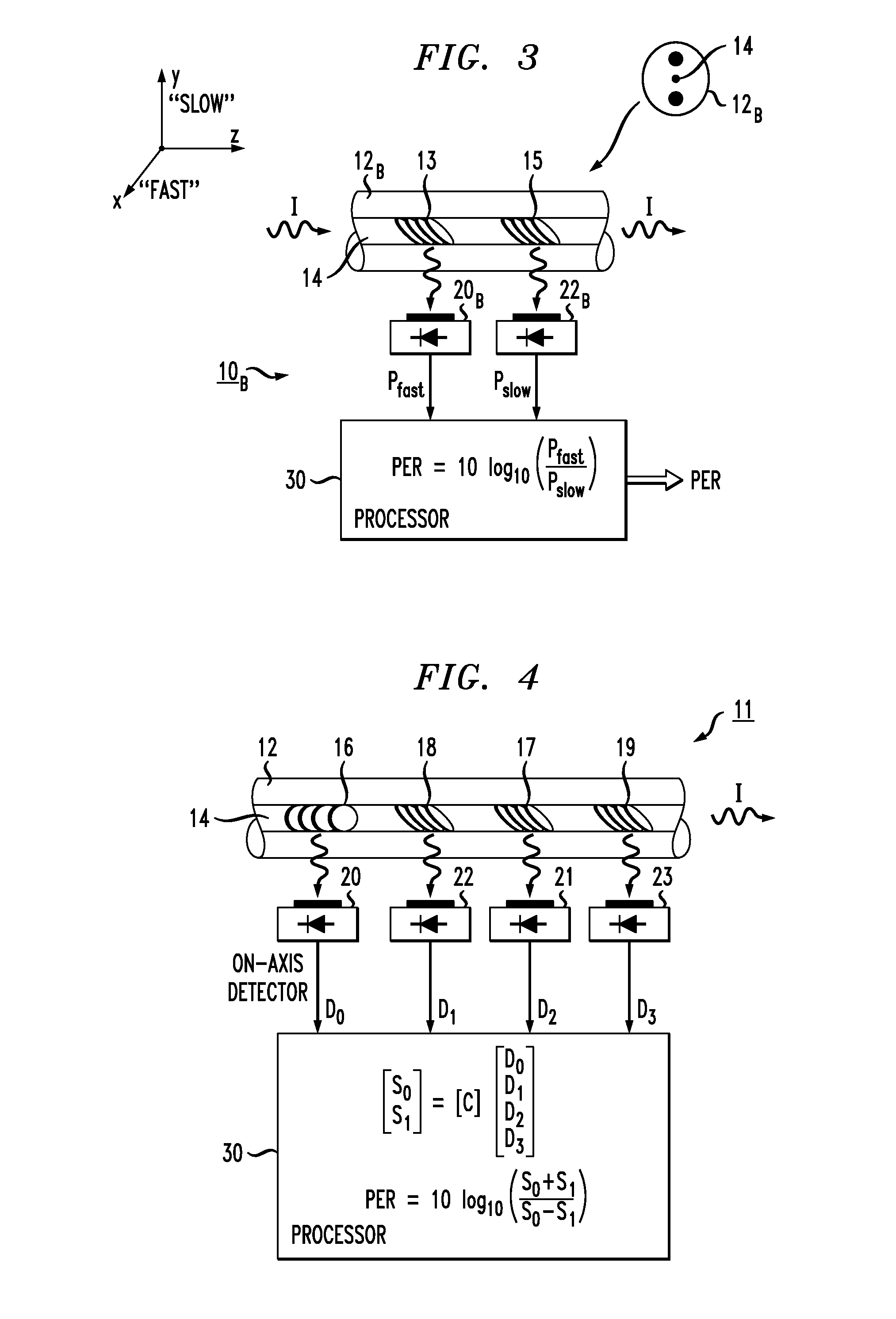
An in-line polarization extinction ratio (PER) monitor that generates a value of an optical signal's PER from a single measurement, without requiring the optical transmission signal path of the system to be directly coupled into a separate measurement device. The polarization extinction ratio may be defined as: 10 log(PEx / PEy), where PEx is the power of the optical signal propagating along the “x axis” and PEy is the power propagating along the orthogonal “y axis” (with the z-axis defined as a longitudinal optical axis of the system and the x-y plane orthogonal to this direction of propagation). The PER monitor comprises a section of optical fiber (preferably birefringent or with induced birefringency), with a pair of gratings formed along the fiber and oriented to out-couple orthogonal components of the propagating signal. Photodetectors are used to convert the scattered light into electrical signal equivalents and then processed to yield the PER value. By properly aligning the axes of the monitor and the optical system, the two measurements are sufficient to provide a one-shot, real-time calculation of the PER of the optical signal propagating through the system.

Description

CROSS-REFERENCE TO RELATED APPLICATIONS[0001]This application claims the benefit of U.S. Provisional Application No. 61 / 506,632, filed Aug. 4, 2011 and herein incorporated by reference.TECHNICAL FIELD[0002]The present invention relates to a technique for measuring the polarization extinction ratio of a propagating optical signal and, more particularly, to an in-line measurement technique that provides a real-time, one-shot measurement of the signal's polarization extinction ratio.BACKGROUND OF THE INVENTION[0003]Many types of fiber-based communication systems rely on the use of polarization-sensitive components to perform a variety of functions. These components include, but are not limited to, polarization-diversity optical transmitters and receivers, polarization-sensitive optical modulators, amplifiers, lengths of polarization-maintaining (PM) fiber and the like. In order to maintain the polarization integrity of the systems, these components are often interconnected using PM fib...

Claims


Application Information

Patent Timeline
IPC IPC(8): G01J4/04
CPCG01J4/04G01J1/0425G01M11/337G01M11/35G02B6/02076G02B6/024
Inventor MIKHAILOV, VITALYWESTBROOK, PAUL S
Owner OFS FITEL LLC
Learn More