
High Temperature Substrate Attachment Glass

a substrate attachment and high temperature technology, applied in the field of glass compositions, can solve the problems of affecting the sofc technology, damage to the substrate, and no previously demonstrated glass material has shown the combination of required reflow temperature, melting temperature, chemical compatibility,

Active Publication Date: 2014-07-10
ROBERT BOSCH GMBH
View PDF11 Cites 10 Cited by
  • Summary
  • Abstract
  • Description
  • Claims
  • Application Information

AI Technical Summary

Benefits of technology

The present invention relates to a method for bonding fuel cell components using a glass composition to create a reliable and durable power supply for portable fuel cell systems. The technical effects of this invention include improved strength, reduced force requirements, and compatibility with high-volume production techniques. The method also allows for the use of a glass composition that exhibits required reflow temperature, chemical compatibility, melting temperature, coefficient of thermal explanation, and strength. Prior to the development of this invention, structures often had low strength, leaking, porous, and low-yielding bonding.

Problems solved by technology

These high operating temperatures present some challenges hindering the SOFC technology.
The prior art fuel cell systems incorporate stacks that are prone to developing cracks upon thermal cycling and exhibiting thermal stress-induced failures at interconnects joining the components.
Unfortunately, many glasses have very high viscosities at the desired bonding temperature, which requires excessive force to deform the intermediate frit material, and may damage portions of the substrate.
Furthermore, no previously demonstrated glass material has shown the combination of required reflow temperature, chemical compatibility, melting temperature, coefficient of thermal explanation, and strength.
Prior to development of the disclosed assembly, structures often had low strength, leaking, porous and low-yielding bonding.

Method used


Image

  • High Temperature Substrate Attachment Glass
  • High Temperature Substrate Attachment Glass
  • High Temperature Substrate Attachment Glass

Examples


Embodiment Construction

[0013]Definitions. As used in this description and the accompanying claims, the following terms shall have the meanings indicated, unless the context otherwise requires:

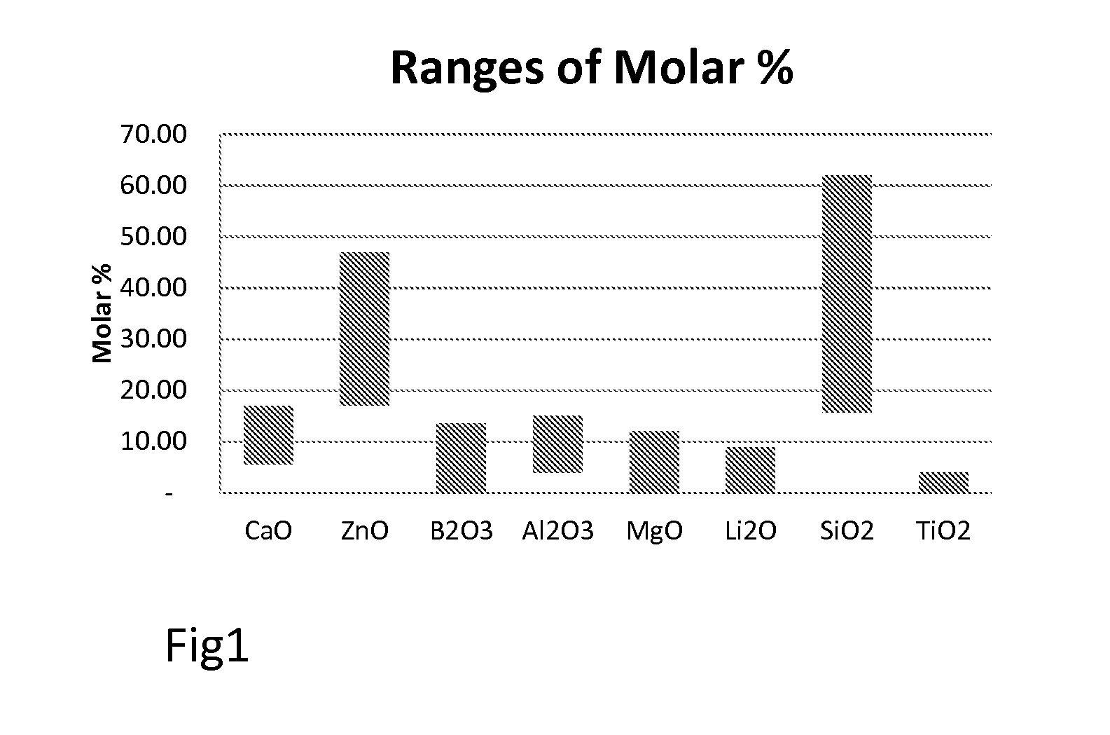
[0014]“Percentage” of components in a glass is described in terms of the molar contribution of the individual oxide unit cell, for example moles of ZnO or Al2O3, as a percentage of the total moles of individual ingredient materials.

[0015]A “substrate” can comprise an object with a plate, cubic, rectangular, or any other geometry containing one or more substantially flat surfaces, composed of ceramic, metal, semiconductor material, or combination thereof.

[0016]“Glass frit” refers to a powdered glass material.

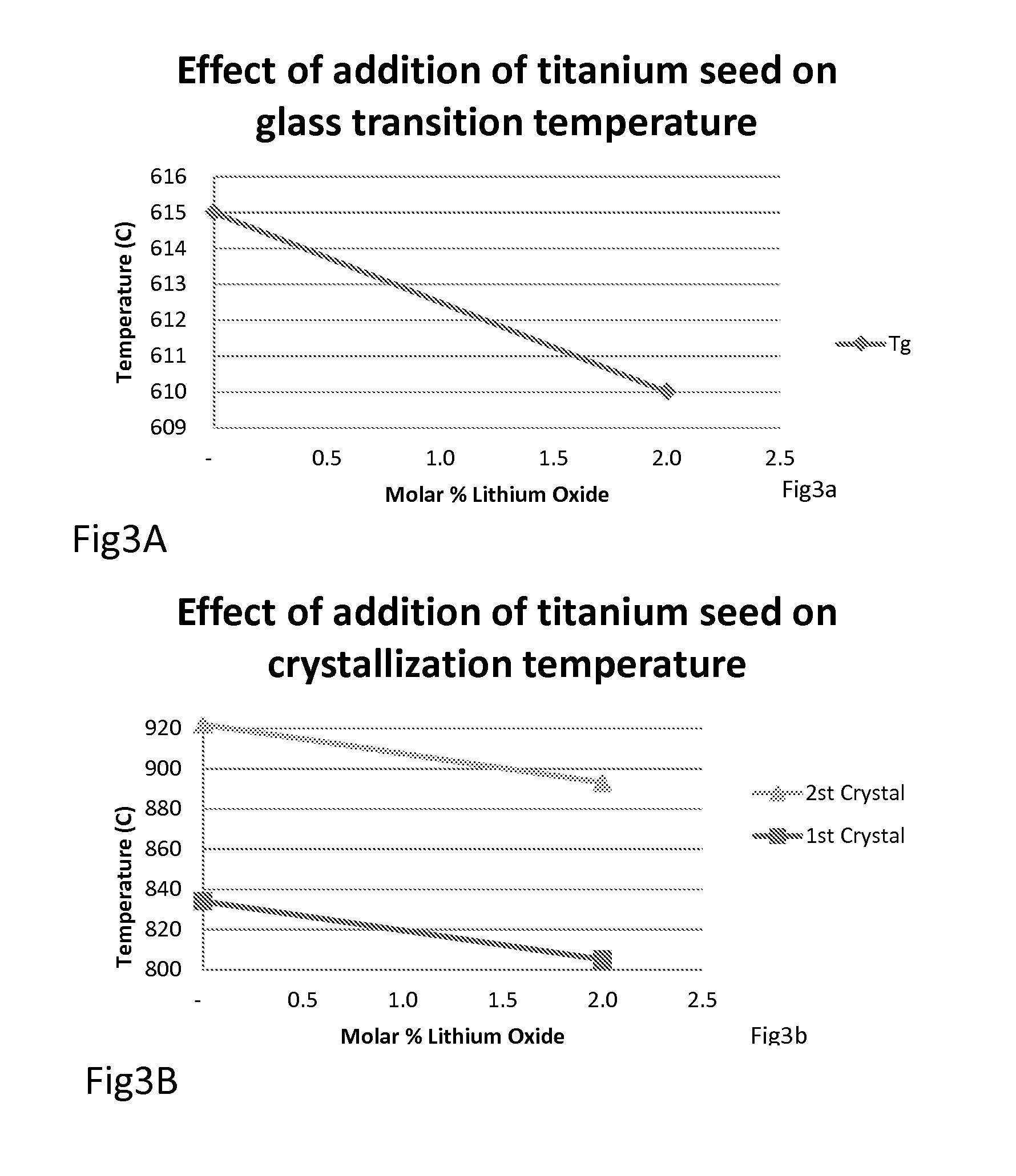
[0017]The “first crystallization temperature” of a glass is the lowest temperature at which the glass experiences an onset of substantial crystallization.

[0018]We have found that the prior disclosed compositions of material shown to bond substrates to one another for high temperature environments can be improved d...


PUM

PropertyMeasurementUnit
glass transition temperatureaaaaaaaaaa
crystallization temperatureaaaaaaaaaa

Abstract

A method of bonding a first substrate to a second substrate includes providing a glass, applying the glass in a layer between the first and second substrates to form an assembly, and heating the assembly to a bonding temperature above a glass transition temperature of the devitrifying glass, selected to cause the glass to bond the first substrate to the second substrate. The devitrifying glass has constituents that include various amounts of group A in a molar concentration of 70-95%, group B in a molar concentration of 5-20%, group C in a molar concentration of 1-20%, group D in a molar concentration of 0-6%; and group E in a molar concentration of 0-10%. The group A, B, C, D and E groups are disclosed herein.

Description

CROSS REFERENCE TO RELATED APPLICATIONS[0001]The present application claims the benefit of U.S. Provisional Application No. 61 / 749,255, filed Jan. 4, 2013, the disclosure of which is incorporated by reference herein in its entirety.TECHNICAL FIELD[0002]The present invention relates to a family of glass compositions, more particularly to bonded assemblies using the glass to form an intermediate layer to attach two or more substrates, and most particularly to a method of forming a stack of substrates for use in a fuel cell.BACKGROUND ART[0003]Fuel cells produce electricity from chemical reactions. The chemical reactions typically cause a fuel, such as hydrogen, to react with oxygen to produce water vapor as a primary by-product. The hydrogen can be provided directly, in the form of hydrogen gas or liquid, or can be produced from other materials, such as hydrocarbon liquids or gasses. Fuel cell assemblies may include one or more fuel cells in a fuel cell housing that is coupled with a ...

Claims


Application Information

Patent Timeline
Patent Type & Authority Applications(United States)
IPC IPC(8): B32B17/06C03C3/066C03C3/093C03C3/085B32B17/00C03C27/00
CPCB32B17/06B32B17/00C03C3/093C03C3/066C03C3/085C03C27/00C03C8/24C03C10/0045C03C17/3618Y02E60/50H01M8/0282
Inventor AKHTAR, MOHAMMAD MASYOODSCHAEVITZ, SAMUEL B.BRADFORD, MICHAEL C.BYARS, ZACHARYTUCKER, JOSEPH C.
Owner ROBERT BOSCH GMBH
Learn More