
Ballistic arrow

a ballistic arrow and arrow head technology, applied in the field of balls, can solve the problems of affecting reliability, short accounting period, limited design of arrow head, etc., and achieve the effect of adding support and stability, not impeded fligh

Active Publication Date: 2014-07-03
WILLIAM DAVID HAND
View PDF3 Cites 7 Cited by
  • Summary
  • Abstract
  • Description
  • Claims
  • Application Information

AI Technical Summary

Benefits of technology

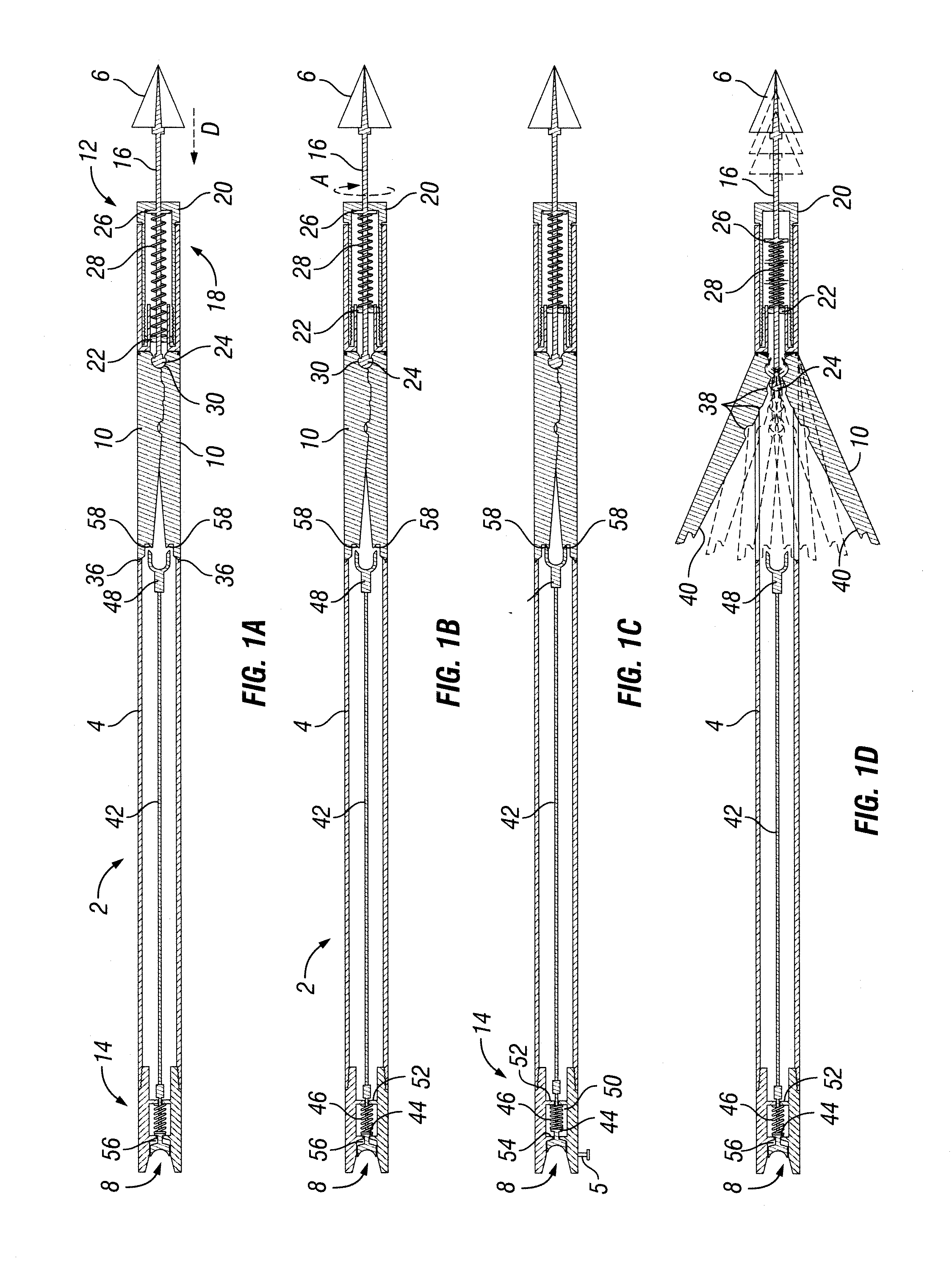
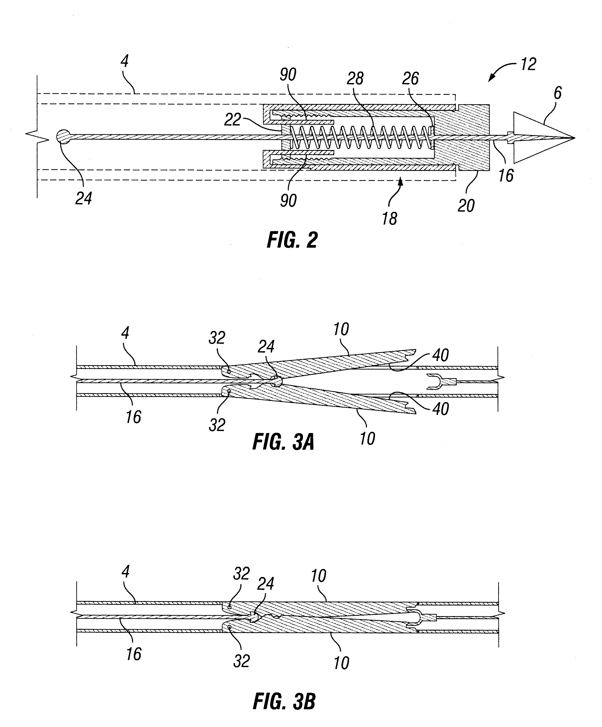
The invention is about a hunting arrow with a special blade design. The blade can be attached to a shaft and can be opened and closed by a sliding tip. The blade has tabs to help it stay in place and also to prevent the shaft from being drawn back too far. The blade can be adjusted to calibrate the delivery of kinetic energy to a target by the size and angle of the blade. The design allows for proper calibration and optimal energy delivery.

Problems solved by technology

Generally, arrow head designs have been limited to small broad heads designed for improved flight, and a one size cutting angle and resulting cutting diameter of the tip.
Conventional designs typically fall short in accounting for these considerations which can, as a result, affect their reliability.
With this loss of efficiency, the mechanical tip of a conventional arrowhead can absorb a disproportionate amount of kinetic energy which otherwise could have been transferred to the target.
Additionally, it is difficult to design a tip that opens inside the target to most effectively damage vital organs.
Being confined to a tip, conventional designs are limited by their overall weight and length due to various competing design considerations.
As such, conventional arrowheads are limited in length and weight thus precluding them from enclosing large blades that are needed for high-speed bow and cross bows, and further limiting their options for properly spacing a combination of a fixed-type design with a mechanical-type design.
Finally, conventional tips are often limited to a single type of a device and cannot accommodate the weight necessary to accommodate a totally integrated solution.
Further, there has been little design variation, even with the development of modern high speed and compound bows, spear guns, and cross bows.
Existing designs do not provide the ability for the archer to adjust the blade angle on the arrow heads to compensate for variable for bow poundage, or for specific target game.
In addition, most current arrow head designs do not provide for a change of blade angles at the time of target penetration to optimize arrow performance for target having different densities.
Additionally, the safety of drawing an arrow and firing an arrow has not been addressed to protect the archer's hand and arm.
Moreover, conventional known arrow heads generally have blades that are fixed in open positions, and lack a safety locking system in place to constrain the blades in a closed position during the draw and fire cycle.
Because the arrow continues moving through and beyond the target, the arrow does not deliver 100% of its kinetic energy to the target.
Any kinetic energy not delivered to the target is wasted.

Method used


Image

  • Ballistic arrow
  • Ballistic arrow
  • Ballistic arrow

Examples


Embodiment Construction

[0072]The foregoing aspects, features, and advantages of the present invention will be further appreciated when considered with reference to the following description of preferred embodiments and accompanying drawings, wherein like reference numerals represent like elements. In describing embodiments of the invention illustrated in the appended drawings, specific terminology will be used for the sake of clarity. However, the invention is not intended to be limited to the specific terms used, and it is to be understood that each specific term may include equivalents that operate in a similar manner to accomplish a similar purpose.

[0073]In accordance with the present invention, there is provided a hunting arrow. The hunting arrow may preferably include parts common to known arrows, such as, for example, arrow vanes. For purposes of simplicity, however, all such features are not shown in the drawings. Multiple arrows are represented in the appended drawings. For example, the invention ...


PUM


Abstract

A hunting arrow having an arrow shaft with a front end and a back end. The hunting arrow has at least one arrow blade attached to the arrow shaft, and has a closed position and at least one open position. The at least one arrow blade is substantially flush with the arrow shaft when in the closed position, and extends radially outward from the arrow shaft when in an open position. In addition, the hunting arrow has an arrow tip that is attached to the front end of the arrow shaft and is capable of moving longitudinally toward or away from the arrow shaft. The arrow tip is operatively engaged with the at least one arrow blade so that the arrow tip opens and closes the at least one arrow blade by moving relative to the arrow shaft.

Description

CROSS-REFERENCES TO RELATED APPLICATIONS[0001]This application is a continuation-in-part of U.S. patent application Ser. No. 13 / 536,033, filed Jun. 28, 2012 and U.S. patent application Ser. No. 13 / 858,160, filed Apr. 8, 2013, which is a continuation of U.S. patent application Ser. No. 13 / 536,349, filed, Jun. 28, 2012, the latter of which is now U.S. Pat. No. 8,414,432 and a continuation of U.S. patent application Ser. No. 13 / 536,033, filed Jun. 28, 2012. The present application claims priority to provisional application 61 / 810,530 filed Apr. 10, 2013, and provisional application 61 / 921,570, filed Dec. 30, 2013. The contents of the aforementioned applications are incorporated herein by reference in their entirety.FIELD OF THE INVENTION[0002]The present invention relates generally to arrows used for hunting. In particular, the invention relates to (a) hunting arrows having blades that deploy, or that separate into multiple parts, upon impact with a target; and (b) hunting devices that...

Claims


Application Information

Patent Timeline
IPC IPC(8): F42B6/08
CPCF42B6/04F42B6/08
Inventor HAND, WILLIAM DAVID
Owner WILLIAM DAVID HAND
Learn More