
Prefabricated Vertical Data Center Modules and Method of Large-Scale Deployment

a data center module and prefabricated technology, applied in the field of data centers, can solve the problems of increasing the power density of computer packaging, the greatest limiting factor of scalability and flexibility in data centers, and the inability to achieve the limited form of scalability and flexibility

Inactive Publication Date: 2014-06-12
VERT COM
View PDF2 Cites 19 Cited by
  • Summary
  • Abstract
  • Description
  • Claims
  • Application Information

AI Technical Summary

Benefits of technology

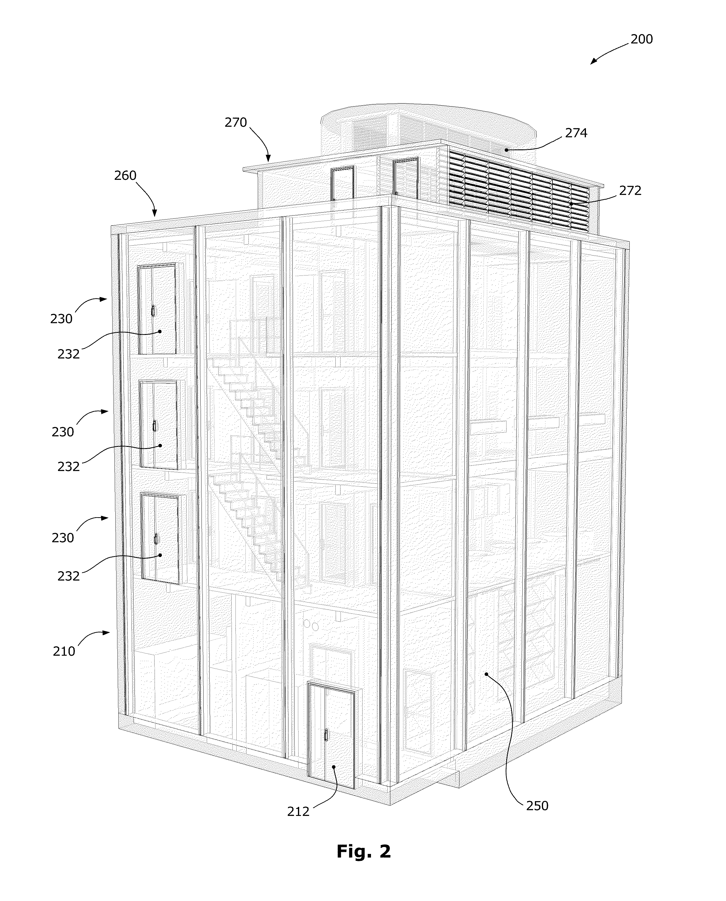
The present invention provides a data center module that overcomes the shortcomings of prior data centers by being configured to accommodate both cooling and electric subsystems and be deployed with other identical modules around a central shared facility. The module has a compact-footprint weatherproof envelop and a multistory energy-efficient layout capable of powering and cooling typical computer hardware. The module includes a reliable low or medium voltage power feeds that can efficiently be carried over distances of several hundreds of feet to modules. The cooling system combines the efficiency of both air-side and water-side economizers and can efficiently operate partially in both modes. The vertical multistory configuration increases efficiency and reliability, while using a small number of large mechanical components.

Problems solved by technology

Recent power density increases in computer packaging are amongst the greatest limiting factors of scalability and flexibility in data centers.
In this way, a limited form of scalability and flexibility can be reached, negating the need to overprovision the whole computing room with the highest possible power density capability.
Nevertheless, forcing these zones to be sized a priori is hardly modular.
The problem lies with the conventional data center design where a huge computing room is surrounded by proportionally sized mechanical and electrical rooms.
Such arrangements are difficult to scale, because large distances limit our ability to efficiently distribute low voltage power to computing machinery, and move enough air to keep this machinery cool.
Too much air velocity brings turbulence that in turn produces pressure differentials and, thus, non uniform air distribution and poor cooling efficiency.
However, bringing water all the way to the computer cabinet (or even inside the cabinets) creates other challenges like leak detection and proofing.
Although this approach can be very modular and, to some extent, scalable, it is not so much flexible.
The physical dimensions of a standard shipping container impose severe space constraints that usually limit the computer form factors that can be hosted while rendering hardware maintenance operations more difficult.
In practice, however, even though rapid initial deployment is an obvious competitive advantage, rapid redeployment is a rare requirement because of the relative short lifespan of computers.
Moreover, there is the additional issue of the low voltage power feeds usually required by these containers that have limited space for in-container power transformation.
For large scale configurations, this forces either to inefficiently carry low voltage energy over large distances, or to combine computing containers with power transformation containers.
The two main sources of power losses in data centers lie in voltage transformation and regularization, on the one hand, and heat disposal, on the second hand.
Also, it is important to correctly size the electrical infrastructure according to effective needs, as underutilized electrical systems are usually less efficient.
The holistic problem, however, is how to design cost-effective and energy efficient data centers that are also modular, scalable, and flexible.

Method used


Image

  • Prefabricated Vertical Data Center Modules and Method of Large-Scale Deployment
  • Prefabricated Vertical Data Center Modules and Method of Large-Scale Deployment
  • Prefabricated Vertical Data Center Modules and Method of Large-Scale Deployment

Examples


Embodiment Construction

[0034]Novel prefabricated data center modules and a method of their large-scale deployment will be described hereinafter. Although the invention is described in terms of specific illustrative embodiments, it is to be understood that the embodiments described herein are by way of example only and that the scope of the invention is not intended to be limited thereby.

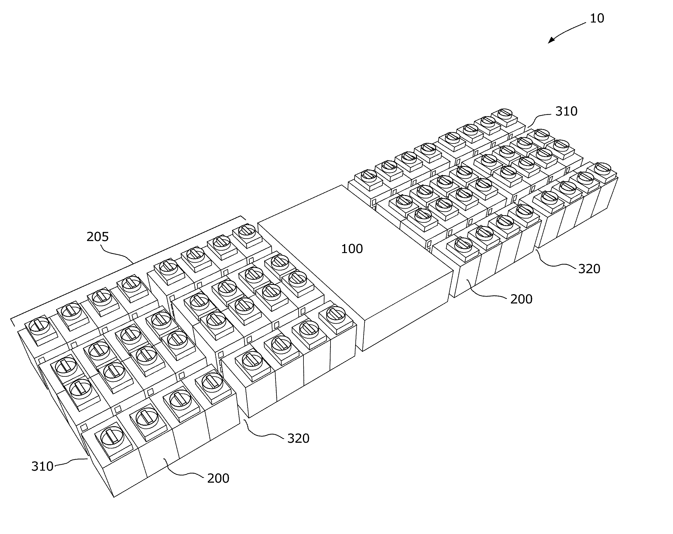
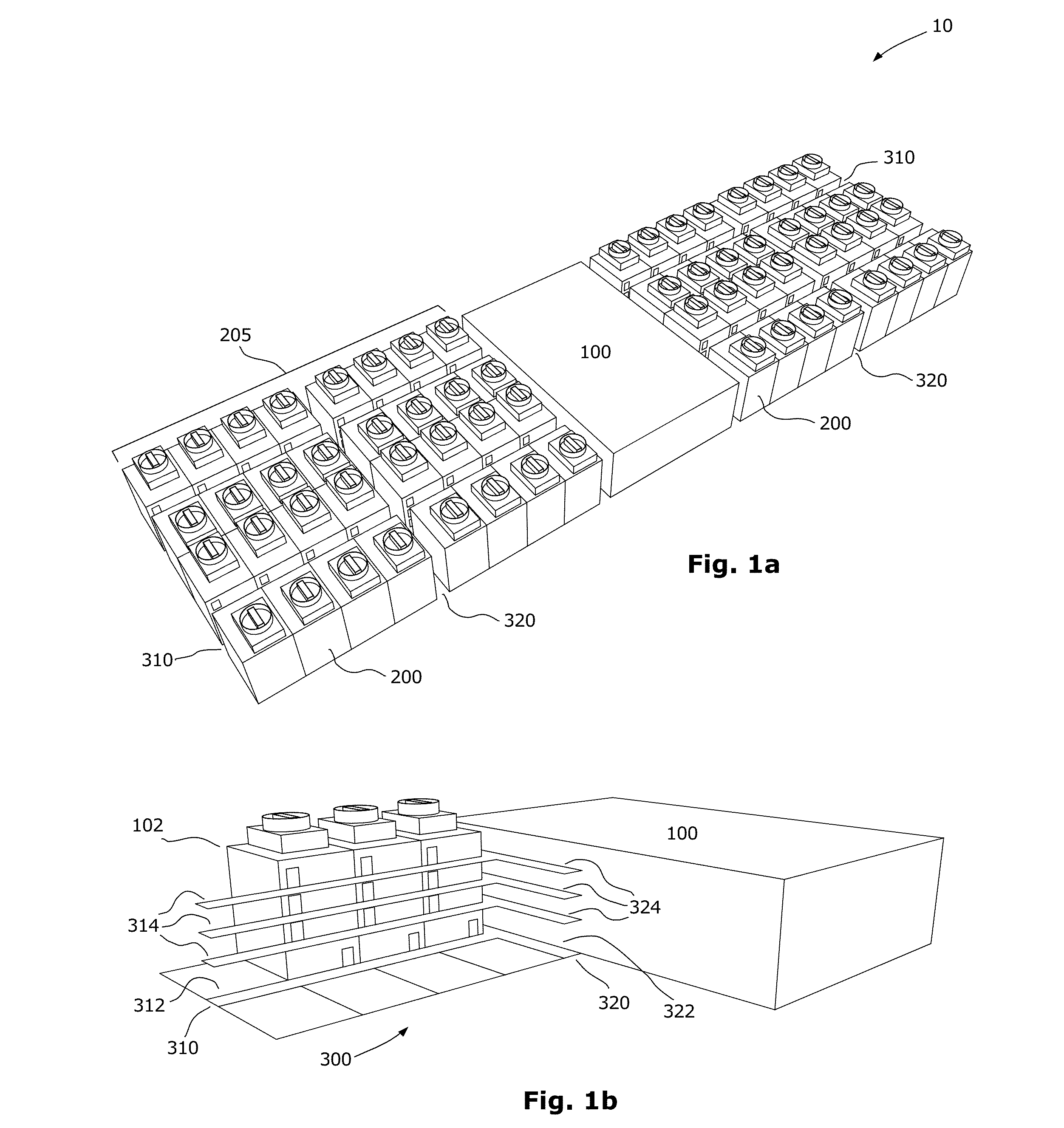
[0035]Referring to FIG. 1a, a module-based data center complex is shown at 10 to be composed of a main facility building 100 surrounded by clusters 205 of prefabricated data center modules or units 200. In this case, 2 clusters 205 of 32 modules 200 each. The central facility 100 hosts the services that are shared by the modules 200: low or medium voltage power feeds, chilled-water feeds, demineralized water for humidity control, Internet connections, security check points with biometric access controls, washrooms, meeting rooms, etc.

[0036]The data center modules 200 are linked to the central facility 100 by a grid of corr...


PUM


Abstract

A data center module is a data center that can be prefabricated using generally standardized off-the-shelf components, and quickly assembled on a collocation site where a shared central facility is provided. The data center module is typically configured to be deployed with other identical data center modules around the central facility both in side-to-side and / or in back-to-back juxtapositions, typically without the need for interleaving space between adjacent modules in order to maximize real estate use. Each data center module typically comprises harden party walls, several floors for accommodating all the necessary electrical and cooling subsystems and for accommodating all the computing machinery (e.g. servers). Though all the data center modules share similar physical configuration, each data center module can be independently customized and operated to accommodate different needs. Each data center module also incorporates a highly efficient hybrid cooling system that can benefit from both air-side and water-side economizers.

Description

CROSS-REFERENCE TO RELATED APPLICATIONS[0001]The present patent application claims the benefits of priority of U.S. Provisional Patent Application No. 61 / 736,270, entitled “Prefabricated Energy Efficient Data Center Condominiums and Method of Large Scale Deployment” and filed at the United States Patent and Trademark Office on Dec. 12, 2012. The content of which is incorporated herein by reference.FIELD OF THE INVENTION[0002]The present invention generally relates to data centers and more particularly to modular data centers and data center modules.BACKGROUND OF THE INVENTION[0003]Modularity, scalability and flexibility are now essential requirements for efficient and cost effective data centers. Modularity is the building block that allows rapid on-demand deployment of infrastructures. Modularity minimizes capital expenditure and, thus, maximizes return on investment (ROI). Scalability relates to modularity, but is the additional key that enables a design to scale past the barrier ...

Claims


Application Information

Patent Timeline
Patent Type & Authority Applications(United States)
IPC IPC(8): E04H1/00
CPCE04H1/005E04H5/00E04H2005/005H05K7/1497H05K7/20745H05K7/2079H05K7/20836
Inventor PARIZEAU, MARCMATEU-HUON, ERICSAVARD, PHILIPPE
Owner VERT COM
Learn More