
Finfet and method of fabricating the same

a technology of transistors and fins, applied in the field of integrated circuit fabrication, can solve problems such as degrading device performance, challenging the implementation of such features and processes, and affecting device performan

Active Publication Date: 2014-05-15
TAIWAN SEMICON MFG CO LTD
View PDF7 Cites 11 Cited by
  • Summary
  • Abstract
  • Description
  • Claims
  • Application Information

AI Technical Summary

Benefits of technology

The patent text discusses the challenges of creating higher performance semiconductor devices as the industry progresses towards nanometer technology. To overcome these challenges, the text introduces the concept of a fin field effect transistor (FinFET), which consists of a thin vertical fin that extends from a substrate and is used to form the channel of the transistor. A gate is provided over the fin, allowing for control of the channel from both sides. The text also mentions the use of strained materials to enhance carrier mobility in the FinFET. In summary, the patent introduces a new technology to overcome challenges in semiconductor fabrication and design and proposes a solution for creating higher performance semiconductor devices.

Problems solved by technology

As the semiconductor industry has progressed into nanometer technology process nodes in pursuit of higher device density, higher performance, and lower costs, challenges from both fabrication and design issues have resulted in the development of three-dimensional designs, such as a fin field effect transistor (FinFET).
However, there are challenges to implementation of such features and processes in complementary metal-oxide-semiconductor (CMOS) fabrication.
For example, non-uniform distribution of silicide on strained materials causes high contact resistance of source / drain regions of the FinFET, thereby degrading the device performance.

Method used


Image

  • Finfet and method of fabricating the same
  • Finfet and method of fabricating the same
  • Finfet and method of fabricating the same

Examples


Embodiment Construction

[0008]It is understood that the following description provides many different embodiments, or examples, for implementing different features of the disclosure. Specific examples of components and arrangements are described below to simplify the present disclosure. These are, of course, merely examples and are not intended to be limiting. For example, the formation of a first feature over or on a second feature in the description that follows may include embodiments in which the first and second features are formed in direct contact, and may also include embodiments in which additional features may be formed between the first and second features, such that the first and second features may not be in direct contact. In addition, the present disclosure may repeat reference numerals and / or letters in the various examples. This repetition is for the purpose of simplicity and clarity and does not in itself dictate a relationship between the various embodiments and / or configurations discuss...


PUM


Abstract

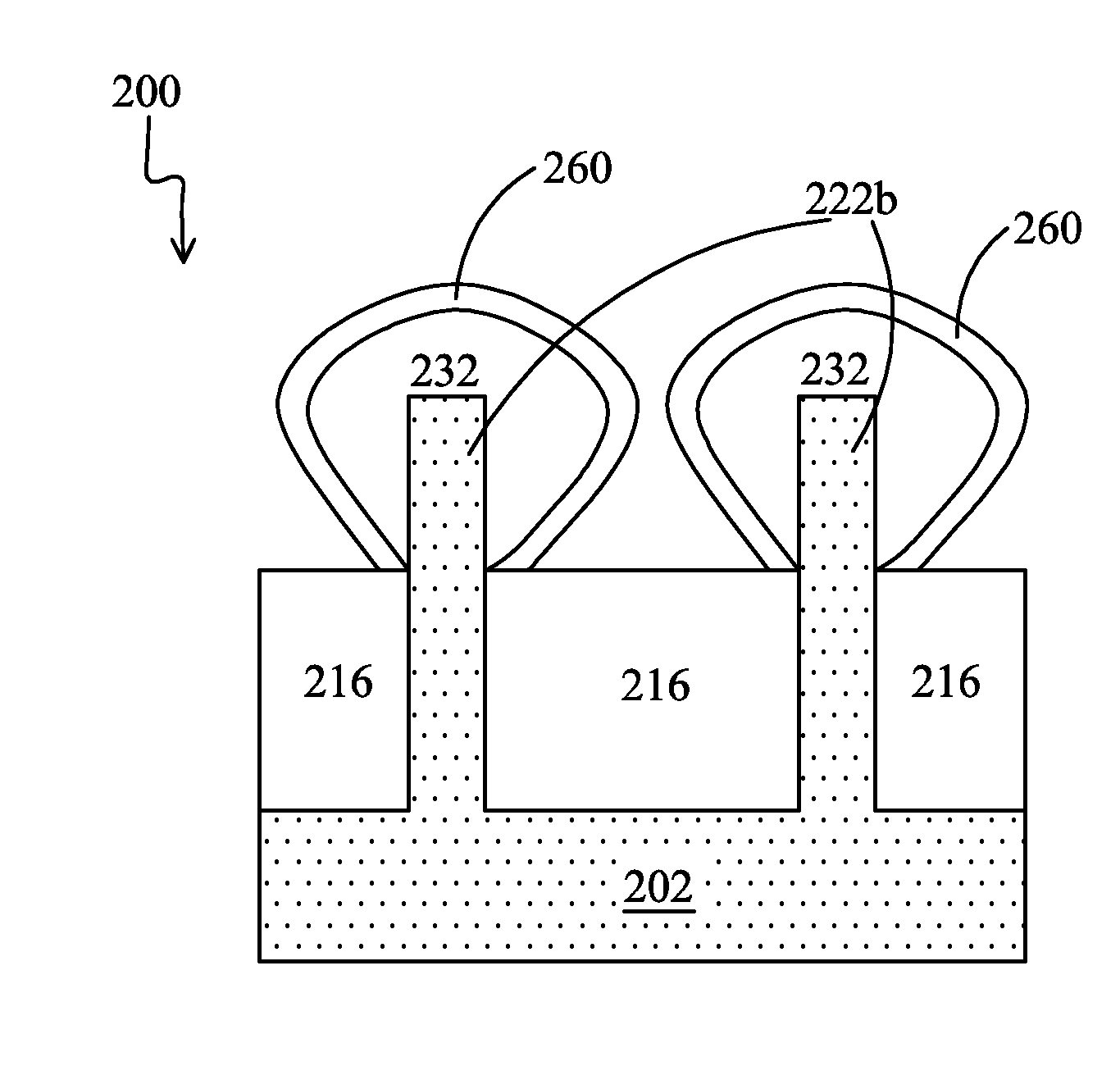
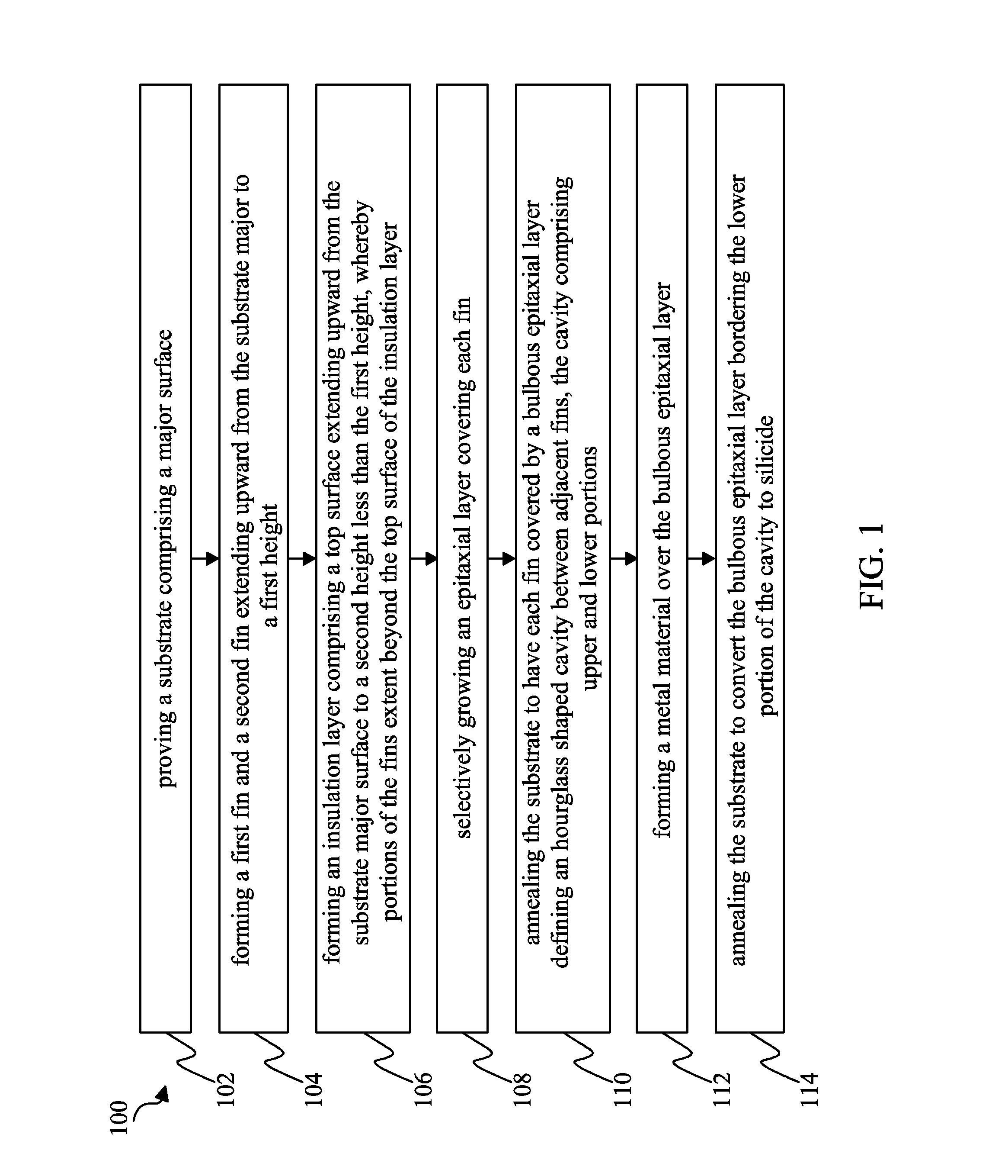
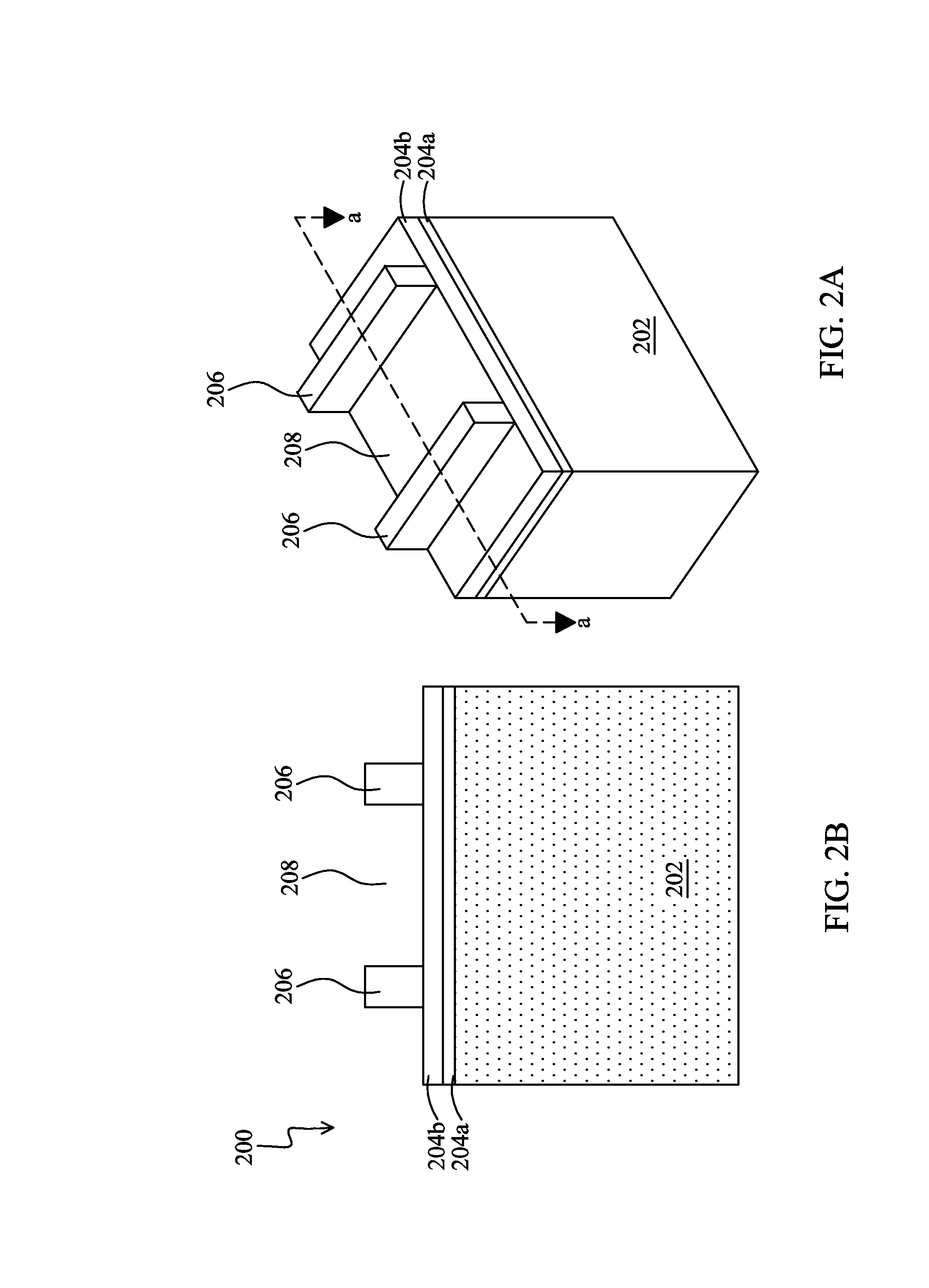
A method of fabricating a fin field effect transistor (FinFET) comprises providing a substrate comprising a major surface, forming a first and second fin extending upward from the substrate major surface to a first height, forming an insulation layer comprising a top surface extending upward from the substrate major surface to a second height less than the first height, wherein a portion of the first and second fin extend beyond the top surface of the insulation layer. The method also includes selectively growing an epitaxial layer covering each fin, annealing the substrate to have each fin covered by a bulbous epitaxial layer defining an hourglass shaped cavity between adjacent fins, wherein the cavity comprises an upper and lower portion. The method includes forming a metal material over the bulbous epitaxial layer and annealing the substrate to convert the bulbous epitaxial layer bordering the lower portion of the cavity to silicide.

Description

PRIORITY CLAIM[0001]The present application is a divisional of U.S. application Ser. No. 13 / 363,003, filed Jan. 31, 2012, which is incorporated by reference herein in its entirety.TECHNICAL FIELD[0002]The disclosure relates to integrated circuit fabrication and, more particularly, to a fin field effect transistor (FinFET).BACKGROUND[0003]As the semiconductor industry has progressed into nanometer technology process nodes in pursuit of higher device density, higher performance, and lower costs, challenges from both fabrication and design issues have resulted in the development of three-dimensional designs, such as a fin field effect transistor (FinFET). A typical FinFET is fabricated with a thin vertical “fin” (or fin structure) extending from a substrate formed by, for example, etching away a portion of a silicon layer of the substrate. The channel of the FinFET is formed in this vertical fin. A gate is provided over (e.g., wrapping) the fin. Having a gate on both sides of the chann...

Claims


Application Information

Patent Timeline
IPC IPC(8): H01L21/02
CPCH01L21/02664H01L21/02532H01L29/66795H01L29/785H01L21/823431H01L27/0886H01L21/02636H01L21/324H01L21/823814H01L29/41791
Inventor CHAO, DONALD Y.CHEN, HOU-YUYANG, SHYH-HORNG
Owner TAIWAN SEMICON MFG CO LTD
Learn More