
Porous carbon monoliths templated by pickering emulsions

a pickering emulsion and porous carbon monolith technology, which is applied in the direction of ceramics, catalyst carriers, other chemical processes, etc., can solve the problems of high cost consideration, high processing cost, and low solids loading in the above-described particle-stabilized system, and achieve the effect of mechanical strength and pore size distribution

Inactive Publication Date: 2014-05-01
CABOT CORP
View PDF2 Cites 34 Cited by
  • Summary
  • Abstract
  • Description
  • Claims
  • Application Information

AI Technical Summary

Benefits of technology

This patent is about a new method for making carbon monoliths, which are materials with a porous structure. The method involves using higher concentrations of carbon aggregates in emulsions, without burning off the carbon. Instead, a small amount of a carbon-containing resin is used to link individual particles, which is then carbonized to create the porous carbon monolith. The resulting monoliths have desirable mechanical strengths and pore size distributions, and can also have bimodal pore size distributions, which are useful for chromatographic separations and electrochemical devices. The invention allows for a deliberate design of the porous structure, with control over pore size and connectivity. Flexibility is achieved in the level of mesoporosity, which can be increased by using high surface area and high structure carbon blacks.

Problems solved by technology

Carbon nanotubes, for example, often are generated in the laboratory or on a small scale, requiring complex procedures and equipment and raising significant cost considerations.
In addition, existing approaches often rely on hazardous materials such as liquid halogens, blowing agents and others.
Moreover, the solids loading in the particle-stabilized systems described above are low.
Higher particle loadings increase the viscosity of the emulsion, making it difficult to achieve uniform mixing.
However, this limits the flexibility of synthesis techniques and the ability to use the solid particle to control pore size distribution.
In addition, low solids loadings can limit the mechanical stability of the resulting dry foam.
In addition, the pore size distributions in many of the systems described above are unimodal.
Such systems may not be able to accommodate different materials having dramatically different sizes.

Method used


Image

  • Porous carbon monoliths templated by pickering emulsions
  • Porous carbon monoliths templated by pickering emulsions
  • Porous carbon monoliths templated by pickering emulsions

Examples


example 1

[0214]This example was carried out to study the formation of pH responsive, reversible Pickering emulsions using surface modified carbon black particles.

[0215]10 ml of water and 4 drops (approximately 0.2 grams) of a sodium salt of p-aminobenzoic acid-modified CB having a BET specific surface area of 200 m2 / g (CAS Number 1106787-35-2; carbon black, (4-carboxyphenyl)-modified sodium salt) dispersed at 15 wt % in water were added to a first 15 ml glass vial. The resultant dispersion was instantly miscible and had a pH of approximately 7.5.

[0216]Heptane (3 ml) was then added to the dispersion. The heptane immediately formed an immiscible layer on the top of the dispersion. The sample was then vortex mixed. Immediately after mixing, the sample appeared homogeneous. After resting for 5 minutes, the sample separated into two layers and appeared as it had before mixing.

[0217]The same procedure was repeated to a second 15 ml glass vial. Additionally, before the addition of heptane, 1 N HCl ...

example 2

[0221]This example was carried out to study the formation of carbon monoliths templated by pickering emulsions.

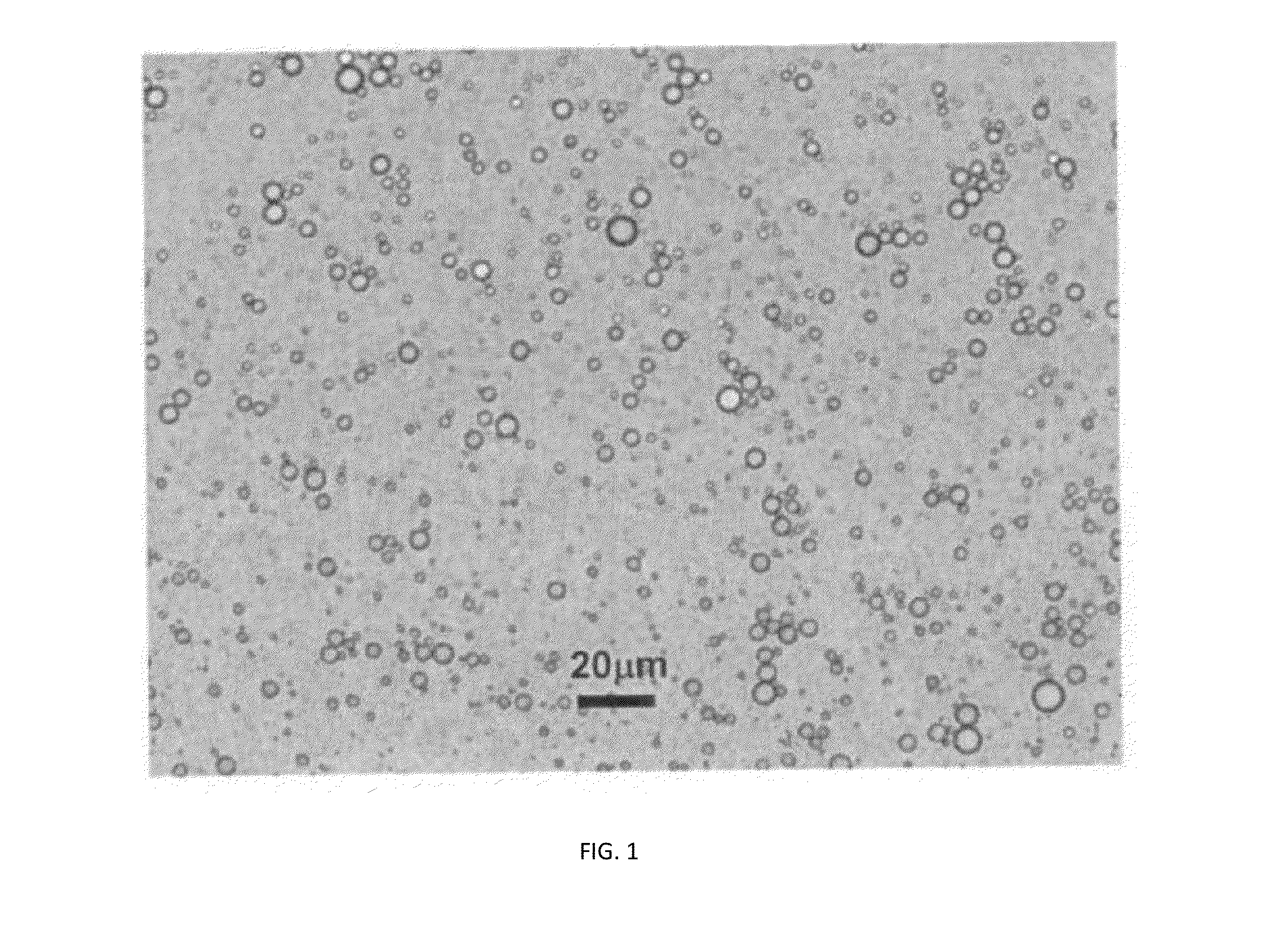
[0222]22.4 g Dynachem phenalloy 7700 resin solution was added to 200 ml of a sodium salt of p-aminobenzoic acid-modified CB having a BET specific surface area of 200 m2 / g (CAS Number 1106787-35-2; carbon black, (4-carboxyphenyl)-modified sodium salt) dispersed at 15 wt % in water. The resultant ratio of resin to carbon black was 40% wt / wt. The resin served as a binder. 2.2 ml of 1 N HCl was then added and the solution was mixed in a Waring blender, Model 31B219. This treatment increases the viscosity of the carbon black dispersion. Addition of HCl protonates acidic sites on the surface of the carbon black, thus reducing the hydrophobicity of this surface and leading to coagulation of some of the particles. 100 ml of octane was then added to the dispersion in 10 ml increments, with 30 seconds of blending at medium speed following each addition. The emulsion appeared uniform ...

example 3

[0227]This example was carried out to determine the compression modulus of porous carbon monoliths according to the invention.

[0228]Samples were prepared as follows. 22.4 g Dynachem phenalloy 7700 resin solution was added to 200 ml of a sodium salt of p-aminobenzoic acid-modified CB having a BET specific surface area of 200 m2 / g (CAS Number 1106787-35-2; carbon black, (4-carboxyphenyl)-modified sodium salt) dispersed at 15 wt % in water. The resultant ratio of resin to carbon black was 40% wt / wt. 2.2 ml of 1 N HCl was then added and the solution was mixed in a Waring blender, Model 31B219. 100 ml of octane was then added to the dispersion in 10 ml increments, with 30 seconds of blending at medium speed following each addition.

[0229]The emulsion was transferred into aluminum dish for air drying. After water and oil evaporated the monolith was heat treated in a furnace at 1000° C. for 2 hours under nitrogen gas.

[0230]The compressive properties of the porous carbon monolith samples wer...


PUM

PropertyMeasurementUnit
Temperatureaaaaaaaaaa
Percent by massaaaaaaaaaa

Abstract

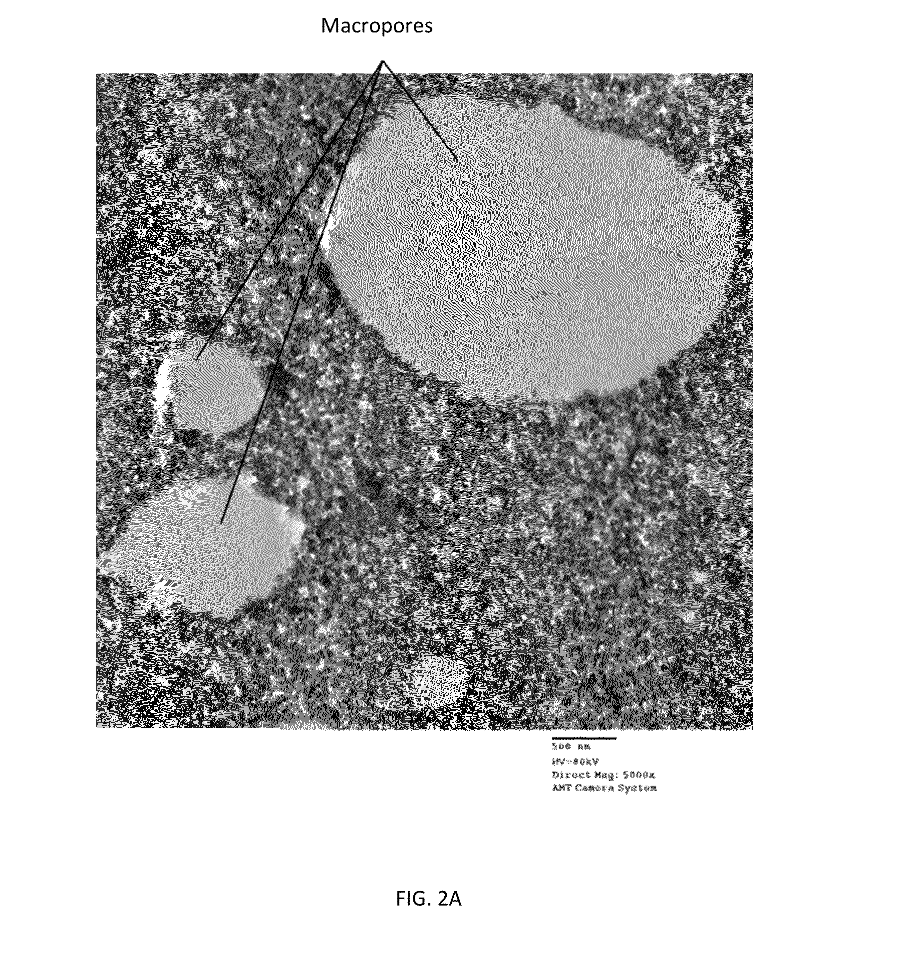
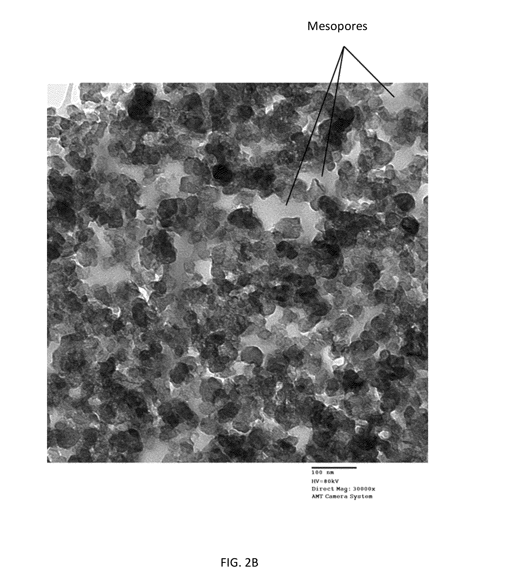
Porous carbon monoliths are prepared using emulsions stabilized by carbonaceous particles or aggregates. An illustrative porous carbon monolith comprises carbon black, including any graphitized carbon black particles, carbonized binder and porosity. The porosity includes first pores having a pore size within the range of from about 0.5 μm to about 100 μm and second pores having a pore size within the range of from about 1 nm to about 100 nm. The pore size distribution of the first pores does not overlap with a pore size distribution of the second pores.

Description

CROSS REFERENCE TO RELATED APPLICATIONS[0001]This patent application claims the benefit of U.S. Provisional Patent Application No. 61 / 720,609, filed Oct. 31, 2012, the entire contents of which are incorporated herein by reference.BACKGROUND OF THE INVENTION[0002]Lithium-ion batteries, catalysis, chromatography and other applications have generated considerable interest in the development of materials having desired properties. Carbon-containing foams, for example, have been prepared using graphite, graphene, and both multi-walled and single-walled carbon nanotubes.[0003]One approach for producing composite polymeric foams that contain multi-walled carbon nanotubes uses blowing agents and surfactants, as described by M. Hermant et al. in the article Conductive Pickering-Poly (High Internal Phase Emulsion) Composite Foams Prepared With Low Loadings of Single-Walled Carbon Nanotubes, published in Chemical Communications 19:2738-2740, 2009. In a different approach (Hermant et al.) compo...

Claims


Application Information

Patent Timeline
IPC IPC(8): B01J20/20B01J20/30B01J32/00
CPCB01J20/20B01J20/3078B01J32/00C04B35/532C04B38/0022C04B2111/0081C04B2111/00853C04B2235/422C04B2235/424C04B2235/48C04B2235/6584Y10T428/249921Y10T428/249967C04B38/0054C04B38/0064
Inventor NIKOVA, ANI T.BOSE, ARIJITSHARMA, RAVI
Owner CABOT CORP
Learn More