
Automobile cell and related method

a technology of automobile cells and cell sheets, applied in the direction of cell components, flat cell groups, sustainable manufacturing/processing, etc., can solve the problems of excessive deformation, adversely affecting the internal structure of the cell or thermally welded portions of the laminate film, and affecting etc., to achieve the effect of improving the welding surface area, reducing the resistance of the whole battery, and improving the welding

Inactive Publication Date: 2014-04-24
ENVISION AESC JAPAN LTD
View PDF5 Cites 0 Cited by
  • Summary
  • Abstract
  • Description
  • Claims
  • Application Information

AI Technical Summary

Benefits of technology

The present invention relates to a battery structure for electric vehicles, hybrid vehicles, and fuel cells. The battery needs to have high power output and energy density, so multiple automobile cells are connected in series or parallel to form a battery for usage. The cells are connected through the use of ultrasonic welding, which allows for easy connection without the need for bolts, reducing resistance and making the battery lightweight. The use of automobile cells that have excellent heat dissipating properties and favorable sealing properties can lower the cost of producing the battery. The battery can be produced by mass producing one or more kinds of automobile cells and utilizing various welding techniques. The battery can also be composed of multiple groups of cells connected in parallel or series to provide different battery capacity and power output for different applications. The cells are arranged in a structure where the electrode terminal leads of the cells are welded to a single sheet of associated bus bar.

Problems solved by technology

Further, with the cell having the cell outer sheath case formed of such a laminate film, since the laminate film has a poor rigidity, it is liable to be readily deformed upon receipt of external forces.
For this reason, it is conceived that excessive deformation may occur and adversely affect on a cell internal structure or thermally welded portions of the laminate film.
More particularly, with the cell in which, as in application such as EV, a large capacity is required, it is conceived that the cell tends to become large in size with consequences in a hard handling or a difficulty o be installed on the vehicle and, in addition, the automobile cell (cells) tends to have an increased thickness to deteriorate a heat dissipating property with a resultant adverse affect caused in a thermal performance with respect to the large electric current.
Also, it is conceived that when repeatedly performing charging and discharging cycles at the large electric current, the temperature of the cell increases due to Joule's heat caused by internal resistance of the cell with a resultant adverse affect caused in a cell performance and the thermally welded portions.

Method used

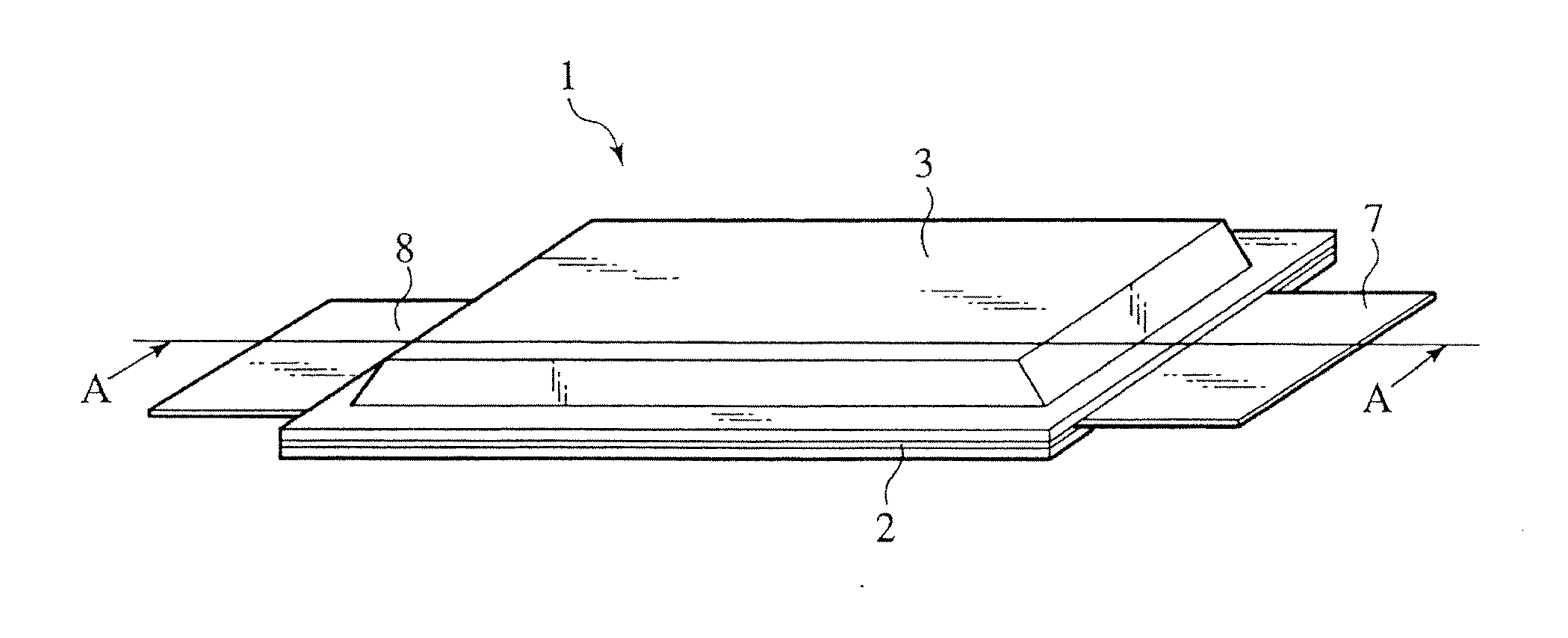
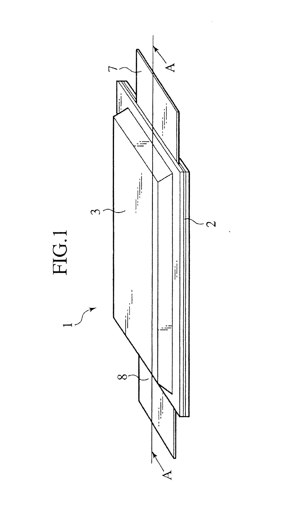
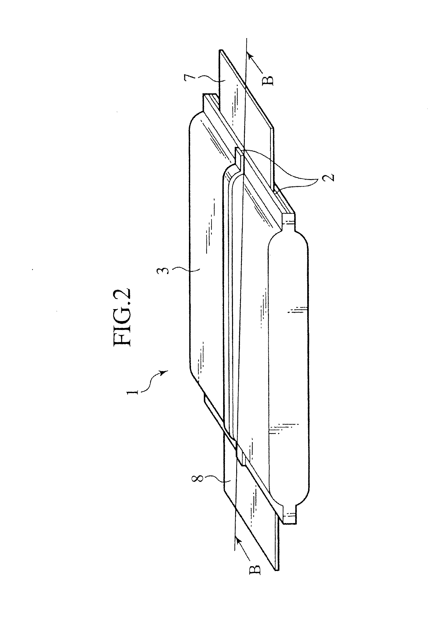

Image

  • Automobile cell and related method
  • Automobile cell and related method
  • Automobile cell and related method

Examples


example 1

[0113]In this Example 1, as shown in FIGS. 1 to 5, a flat type cell of a stack structure was fabricated in a structure wherein the circumferentially peripheral portions of the cell outer sheath material 3 made of polymer-metal composite laminate film with a thickness of 120 (μm) were joined by thermal welding and the positive electrode terminal lead 7 and the negative electrode terminal lead 8 with respective thickness of 100 (μm) and width 80 (μm) are taken out from two points, i.e., from the opposing sides of the thermally welded portions 2.

[0114]In particular, use was made for the positive electrode plate 4 having the positive electrode current collector 4a, made of aluminum foil that has a thickness of 15 (μm) and coated with a slurry including the positive electrode active substance of LiMn2O4 and, in addition thereto, a mixture of PVdF, serving as the binder, and acetylene black serving as the electrically conductive promoting agent and dried to form the positive electrode act...

example 2

[0117]Using the same electrodes as those of Example 1 in the present Example 2, the separators 6 were sequentially sandwiched and stacked between eleven sheets of negative electrode plates 5 and ten sheets of positive electrode plates 4, forming the electric power generating element 9a, to which the positive and negative electrode terminal leads 7, 8 having the thickness T3, T3′ of 200 (μm) and the widths L5, L5′ of 80 (mm) were connected. The resulting electric power generating element 9a was then encapsulated in the outer sheath laminate films 3 whereupon the circumferentially peripheral portions of the cell outer sheath materials 3 were thermally welded, thereby fabricating a flat automobile cell of a stack type.

[0118]A value of the maximum cell thickness T1 / the active substance thickness T2+T2′ of the unit electrode was 29, and a value of the unit cell surface area S7 / the cell capacity CB was 79 (cm2 / Ah). Also, the cell size was L6 (=L6′)×L9×T1=170 (mm)×200 (mm)×3500 (μm). Speci...

example 3

[0119]Using the same electrodes as those of Example 1 in the present Example 3, the separators 6 were sequentially sandwiched and stacked between sixteen sheets of negative electrode plates and fifteen sheets of positive electrode plates, forming the electric power generating element 9a, to which the positive and negative electrode terminal leads 7, 8 with the thickness T3, T3′ of 200 (μm) and the widths L5, L5′ of 80 (mm) were connected. The resulting electric power generating element 9a was then encapsulated in the outer sheath laminate films 3 whereupon the circumferentially peripheral portions of the cell outer sheath materials 3 were thermally welded, thereby fabricating a flat automobile cell of a stack type.

[0120]A value of the maximum cell thickness T1 / the active substance thickness T2+T2′ of the unit electrode was 43, and a value of the unit cell surface area S7 / the cell capacity CB was 50 (cm2 / Ah). The cell size was L6 (=L6′)×L9×T1=170 (mm)×200 (mm)×5100 (μm). Specificatio...


PUM

PropertyMeasurementUnit
lengthaaaaaaaaaa
thicknessaaaaaaaaaa
thicknessaaaaaaaaaa

Abstract

An automobile cell is provided with an electric power generating element composed of a positive electrode having a positive electrode active substance layer, a negative electrode having a negative electrode active substance layer and a separator interposed between the electrodes, a cell outer sheath made of a laminate film compositely composed of polymer and metal, a positive electrode terminal lead electrically conductive with the positive electrode and extending to an outside of the cell outer sheath, and a negative electrode terminal lead electrically conductive with the negative electrode and extending to the outside of the cell outer sheath. The positive electrode and the negative electrode associated therewith via the separator defines a unit electrode, and the relationship between a thickness of the automobile cell and a sum of a thickness of the positive electrode active substance layer and a thickness of the negative electrode active substance layer of the unit electrodes, is defined such that a value obtained by dividing the former by the latter is equal to or less than 80.

Description

CROSS REFERENCE TO RELATED APPLICATIONS[0001]This application is a Continuation application of U.S. Ser. No. 10 / 622,511 filed Jul. 21, 2003 which claims priority from Japanese Patent Application No. P2002-227423 filed Aug. 5, 2002. The subject matter of each is incorporated by reference in entirety.BACKGROUND OF THE INVENTION[0002]The present invention relates to an automobile cell and a related method and, more particularly, to a flat type automobile cell and its related method wherein use is made for a laminate film, compositely made from a polymer and a metal, as a cell outer sheath to provide an optimum structure for application to a drive source for a motor of an electric vehicle, a hybrid vehicle or a fuel cell-powered vehicle, or for application to a storage battery thereof.[0003]In recent years, among increasing trends in which environmental protection movements and air pollutions caused by exhaust gases of automobiles attract public attention worldwide, research and develop...

Claims


Application Information

Patent Timeline
Patent Type & Authority Applications(United States)
IPC IPC(8): H01M10/04H01M2/02H01M2/20B60L11/18H01M4/13H01M6/40H01M10/05H01M10/0585H01M10/0587H01M10/42H01M50/105H01M50/124H01M50/178H01M50/505H01M50/548H01M50/562
CPCH01M10/0413H01M2/206H01M2/024H01M6/40H01M10/0525H01M2004/021H01M2010/4292Y10T29/49114Y10T29/4911Y02E60/10H01M50/124Y02P70/50H01M50/505H01M50/562H01M50/105H01M50/178H01M50/548Y02T10/70
Inventor SHIMAMURA, OSAMUSUGAWARA, HIROSHIHORIE, HIDEAKIOGAWA, TOMARUABE, TAKAAKIITO, TAKANORI
Owner ENVISION AESC JAPAN LTD
Learn More