Eureka AIR delivers breakthrough ideas for toughest innovation challenges, trusted by R&D personnel around the world.

Reactor and process for endothermic gas phase reaction in a reactor

a gas phase reaction and reactor technology, applied in the direction of instruments, silicon compounds, disinfection, etc., can solve the problems of long-term failure of the reactor, and high construction complexity

Inactive Publication Date: 2014-04-17
WACKER CHEM GMBH
View PDF4 Cites 0 Cited by
  • Summary
  • Abstract
  • Description
  • Claims
  • Application Information

AI Technical Summary

Benefits of technology

The patent describes a gas distribution apparatus that reduces damage to heating elements in a reactor, resulting in a longer service life. The apparatus also increases the conversion rate and economic viability of the process. Additionally, the patent discusses the importance of positioning the temperature sensor correctly to ensure accurate measurements. The use of a gas deflection apparatus in the heating region improves the reactor design, increases the reaction space, reduces energy losses, and reduces the formation of by-products. The patent also addresses the issue of potential deviations from the desired reaction temperature and measures to reduce them.

Problems solved by technology

Both the heating elements and the heat exchangers show an increased level of corrosion, which leads to failure of the reactor.
Moreover, the heating elements are subject to greater or lesser corrosion by hydrogen, which can lead in the long term to failure of the reactor.
However, they additionally exhibit the considerable disadvantage that the construction complexity is very high.
In the prior art, there is inhomogeneous attrition of the heating elements, and there are frequent reactor shutdowns because of failed heating elements.

Method used


Image

  • Reactor and process for endothermic gas phase reaction in a reactor
  • Reactor and process for endothermic gas phase reaction in a reactor
  • Reactor and process for endothermic gas phase reaction in a reactor

Examples


example 1

Comparative Example

[0073]For the comparative example, a reactor according to U.S. Pat. No. 4,536,642 was used.

[0074]A gas mixture in the reactant stream consisting of 33 mol % of silicon tetrachloride and 67 mol % of hydrogen was used. The inlet temperature of the reactant gas stream was about 175° C.

[0075]The pressure was set to 6 bar and the temperature of the gas in the reaction zone to 1000° C.

[0076]After the reaction, the product gas was analyzed in a gas chromatograph, and the proportions of trichlorosilane and silicon tetrachloride were determined. The temperature of the exiting product gas stream was about 350° C.

[0077]The relative selectivity is given by the molar proportion of trichlorosilane relative to silicon tetrachloride.

[0078]For the sake of simplicity, the relative selectivity attained in the comparative example is defined as 100% if all heating elements are working.

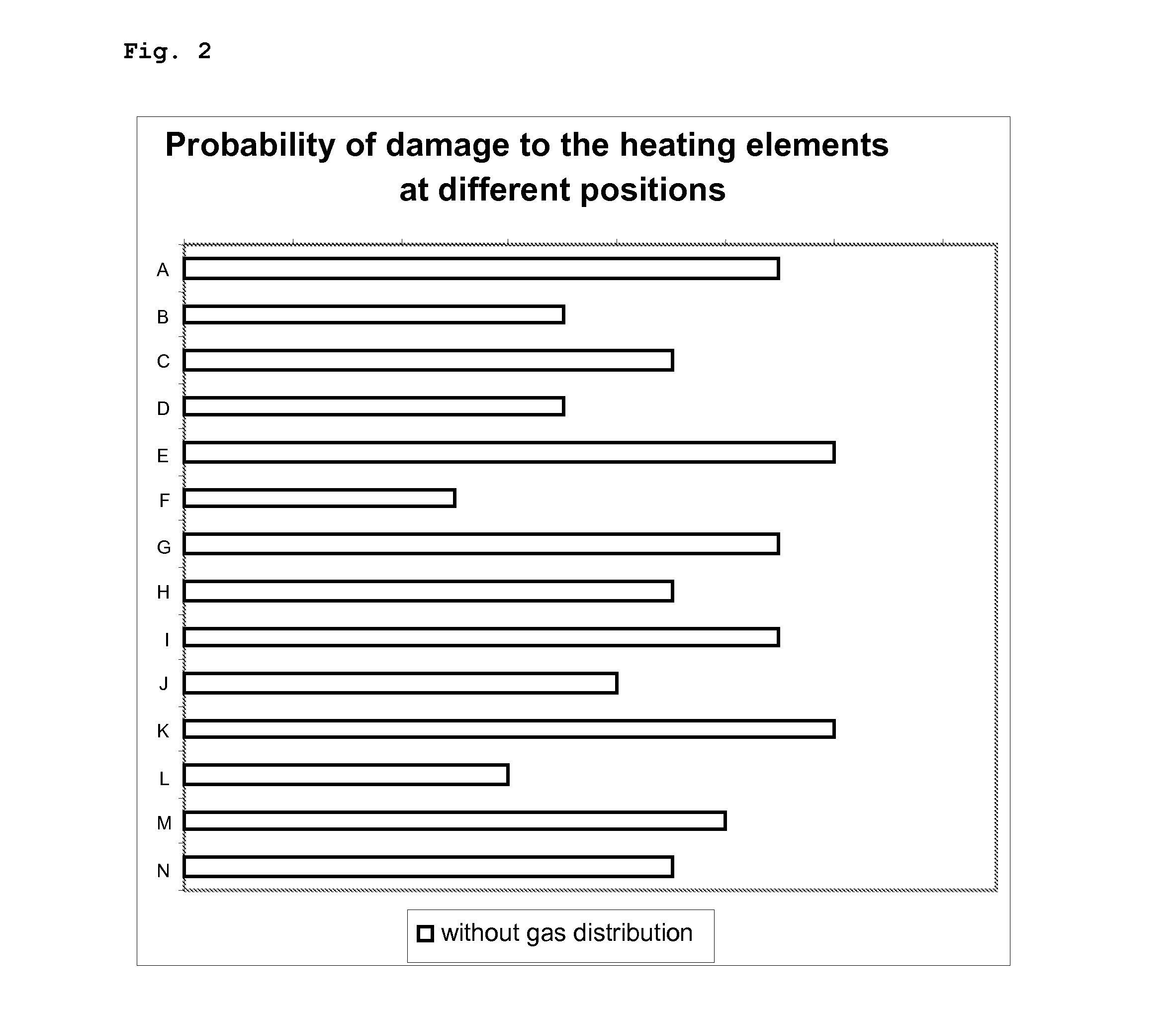
[0079]FIG. 2 shows the relative probability of damage to the individual heating elements as a functio...

example 2

[0085]In Example 2, essentially the same boundary conditions are used as in Example 1.

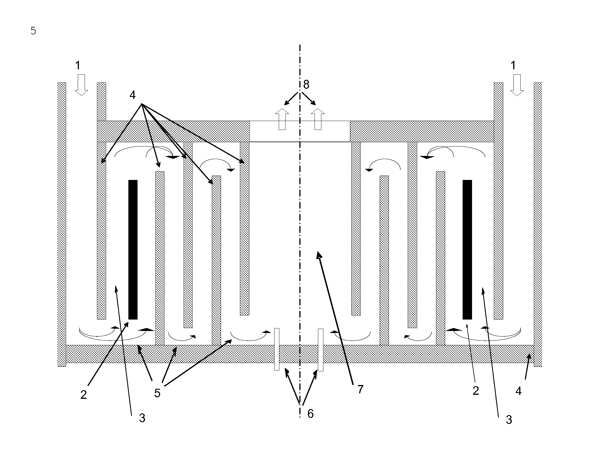
[0086]However, the gas supply is distributed better into the heating zone using a gas distribution apparatus.

[0087]The gas distribution apparatus homogenizes the gas stream fed in over different gas passage dimensions along the gas feed into the cylindrical heating zone.

[0088]FIG. 3 shows a distinct improvement in the probability of damage resulting from the incorporation of a gas distribution apparatus.

[0089]The random cases of damage are altered to become a systematic distribution.

[0090]FIG. 3 additionally shows an inhomogeneous but systematic distribution of the gas phase supplied.

[0091]The relative probability of damage to the heating elements is reduced and the reactor can be operated for longer.

[0092]By virtue of the now systematic gas distribution, it is possible by further optimization steps to adjust and further improve the apparatus for better gas distribution according to the geometry of...

example 3

[0099]In Example 3, essentially the same boundary conditions are used as in Example 1.

[0100]However, the reaction zone is equipped with an additional four temperature measurement devices, such that it is possible to additionally measure the temperature in the reaction zone in a spatially resolved manner.

[0101]The temperature measurement devices are arranged radially around the centre of the base plate within the reaction zone.

[0102]FIG. 1 shows, by way of example, the position of two of these additional temperature measurement devices 6.

[0103]If the determination of the temperature is carried out not as described in Example 1 with only one temperature measurement device but with the mean of all the values from the available temperature measurement devices, it is found that, in the event of failure of a heating element, the relative selectivity falls only to 99.5%, since the direct influence of temperature on the regulation temperature is reduced.

[0104]The unwanted by-products from a...


PUM

PropertyMeasurementUnit
temperatureaaaaaaaaaa

Abstract

The invention provides a process for endothermic gas phase reaction in a reactor, in which reactant gases are introduced into the reactor via a gas inlet apparatus and distributed homogeneously into a heating zone by means of a gas distribution apparatus, wherein the reactant gases are heated in the heating zone to a mean temperature of 500-1500° C. by means of heating elements and then conducted into a reaction zone, the reactant gases reacting in the reaction zone to give a product gas which is conducted out of the reactor via a gas outlet apparatus. Further subject matter of the invention relates to a process for endothermic gas phase reaction in a reactor, wherein the heating of the heating elements is controlled by temperature measurements in the reaction zone, at least two temperature sensors being present in the reaction zone for this purpose, and reactor for performance of the process.

Description

BACKGROUND OF THE INVENTION[0001]The invention provides a reactor and a process for endothermic gas phase reaction in a reactor.[0002]One example of such a reaction is the conversion of silicon tetrachloride (STC) with hydrogen to trichlorosilane (TCS) and HCl. The conversion of STC with hydrogen to trichlorosilane typically takes place in a reactor at high temperatures, at at least 600° C., ideally at at least 850° C. The relative selectivity is given by the molar proportion of trichlorosilane relative to silicon tetrachloride. It is a measure of how much of the STC used is converted to TCS and thus determines the economic viability of the process.[0003]U.S. Pat. No. 4,536,642 A describes an apparatus and a process for conversion of silicon tetrachloride STC to trichlorosilane TCS.[0004]The reactants are introduced into the vessel through the inlet and brought to temperature with the aid of the hot offgas within the three successive heat exchangers. The heating elements heat the re...

Claims


Application Information

Patent Timeline
Patent Type & Authority Applications(United States)
IPC IPC(8): C01B33/107
CPCC01B33/1071B01J4/005B01J2219/00063B01J2219/00135B01J2219/00159B01J2219/002B01J2219/00238
Inventor HIRSCHMANN, ANDREASHAECKL, WALTERPAETZOLD, UWE
Owner WACKER CHEM GMBH
Why Eureka
Eureka Blog
Learn More