
Position indicator

a position indicator and indicator technology, applied in the field of position indicators, can solve the problems of weakening the strength affecting the stability so as to reduce the probability of damage to the magnetic core, reduce the shaft diameter of the position indicator, and improve the stability.

Active Publication Date: 2008-07-31
WACOM CO LTD
View PDF14 Cites 28 Cited by
  • Summary
  • Abstract
  • Description
  • Claims
  • Application Information

AI Technical Summary

Benefits of technology

[0007]The present invention provides a magnetic core for a position indicator having a high shock resistance when the indicator is impacted, such as when it fall or is dropped. More specifically, according to the present invention, the probability of damaging the magnetic core may be lowered. Thus, the position indicator can be simply configured without a buffer material around the core, and a shaft diameter of the position indicator can be reduced.

Problems solved by technology

However, a magnetic core of the position indicator, around which the resonant coil is wound, may be damaged by impact when the position indicator is dropped or falls.
Because the magnetic core utilized in prior position indicator(s) is formed of soft magnetic molded metal product, it is usually fragile against impact.
Thus, the position indicator may not be strong enough to withstand the impact when it is dropped or when the position indicator is forced against a surface by a user's hand.

Method used


Image

  • Position indicator
  • Position indicator
  • Position indicator

Examples


Embodiment Construction

)

[0023]Reference will now be made in detail to the embodiments and methods of the invention as illustrated in the accompanying drawings, in which like reference characters designate like or corresponding parts throughout the drawings. It should be noted, however, that the invention in its broader aspects is not limited to the specific details, representative devices and methods, and illustrative examples shown and described in this section in connection with the preferred embodiments and methods. The invention according to its various aspects is particularly pointed out and distinctly claimed in the attached claims read in view of this specification.

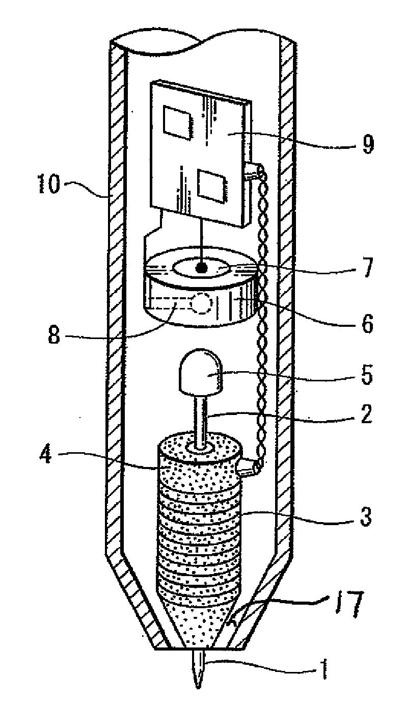
[0024]Japanese Unexamined Patent Application Publication No. 2004-71845 describes a technique used to produce a core of a magnetic device. In this technique, a flat soft magnetic metal powder is mixed with an organic binder to form a core of the magnetic device by injection molding. The technique increases the molding flexibility. Due to...


PUM

PropertyMeasurementUnit
soft magneticaaaaaaaaaa
pressureaaaaaaaaaa
capacitanceaaaaaaaaaa

Abstract

A position indicator for use with a digitizer is provided. The position indicator generates a response to an alternating field received from the digitizer. The position indicator includes a core formed of a composition including a soft magnetic metal powder mixed with a resin binder, and at least one coil provided around the core configured to generate the response to the alternating field based on the alternating field received from the digitizer.

Description

CROSS REFERENCES TO RELATED APPLICATIONS AND CLAIM TO PRIORITY[0001]The present invention contains subject matter related to Japanese Patent Application JP 2007-016648 filed in the Japanese Patent Office on Jan. 26, 2007, the contents of which are incorporated herein by reference and to which priority is claimed.FIELD OF THE INVENTION[0002]The present invention relates to a position indicator suitable for use in a digitizer; which may be connected to a computer. Specifically, the present invention relates to a position indicator having a magnetic core with an improved shock resistance and a decreased diameter of the magnetic core that is easy to manufacture.BACKGROUND OF THE INVENTION[0003]A pen-shaped position indicator generally includes a resonant coil for detecting a position. The resonant coil is arranged in the vicinity of the tip of the pen shape (e.g., see Japanese Unexamined Patent Application Publication No. 2001-319831). However, a magnetic core of the position indicator,...

Claims


Application Information

Patent Timeline
Patent Type & Authority Applications(United States)
IPC IPC(8): G01B7/14G01R33/02H03M1/00B29C45/00
CPCG01D5/208G01D5/24G01D5/2417G06F3/03545G06F3/046H01G5/16H01F3/08H01F17/045H01F41/0246H01F2017/048H01F1/26
Inventor FUKUSHIMA, YASUYUKIFUJITSUKA, HIROYUKI
Owner WACOM CO LTD
Learn More