Carbon dioxide enrichment device

a carbon dioxide and enrichment device technology, applied in the field of carbon dioxide enrichment devices, can solve the problems of large energy consumption, inability to achieve the enrichment performance of carbon dioxide and low energy consumption, etc., and achieve the effects of high carbon dioxide enrichment performance, excellent effect, and reduced energy required during driving

Inactive Publication Date: 2014-04-17
PANASONIC CORP +1
View PDF7 Cites 7 Cited by
  • Summary
  • Abstract
  • Description
  • Claims
  • Application Information

AI Technical Summary

Benefits of technology

[0023]According to the carbon dioxide enrichment device of the present invention, in the constitution including a first gas diffusion electrode, a second gas diffusion electrode, and an electrolytic solution that exists between the first gas diffusion electrode and the second gas diffusion electrode, when a voltage is applied between the first gas diffusion electrode and the second gas diffusion electrode, and carbon dioxide and oxygen are introduced into the first gas diffusion electrode, a reaction occurs in this first gas diffusion electrode, as shown in the above-mentioned [Chemical Formula 2], and HCO3− formed by the [Chemical Formula 2] or CO32− and H2CO3 formed by an equilibrium reaction of HCO3− permeates through the electrolytic solution. Whereby, a reaction occurs in the second gas diffusion electrode, as shown in the above-mentioned [Chemical Formula 3], and thus discharging carbon dioxide and oxygen from the second gas diffusion electrode, leading to the achievement of carbon dioxide enrichment. Therefore, the carbon dioxide enrichment device exert an excellent effect capable of significantly reducing energy required during driving since it has high carbon dioxide enrichment performance and there is no need to heat during releasing carbon dioxide.
[0024]Accordingly, according to the present invention, it is possible to provide a carbon dioxide enrichment device that has high enrichment performance, and also enables a significant reduction in energy required during driving.

Problems solved by technology

The solutions reported in the above prior art documents require a great deal of energy, that is, there exists a need to apply heat during desorption (release) of carbon dioxide or to maintain high temperature during driving, and had a problem that it is impossible to achieve both enrichment performance of carbon dioxide and low energy consumption.

Method used


Image

  • Carbon dioxide enrichment device
  • Carbon dioxide enrichment device
  • Carbon dioxide enrichment device

Examples


example 1

Production of Gas Diffusion Electrode

[0072]A commercially available carbon paper (porosity of 70%, thickness of 0.4 mm) was used as a conductive porous material. In order to improve gas diffusivity, a solution containing 30% by weight of polytetrafluoroethylene (PTFE) dispersed therein was applied on one surface of the carbon paper by a bar coater method, and then the resin was fixed to the carbon paper by firing in a nitrogen atmosphere electric furnace at a temperature of 340° C. for 20 minutes, and thus allowing to undergo water repellent finishing.

[0073]A catalyst paste to be applied on the carbon paper was prepared in the following manner. In a zirconia pot for ball mill, a commercially available platinum-supported carbon black (supporting 10 wt % Pt / Vulcan XC-72) was dispersed in 50 mL of a mixed solvent (2-propanol / water=1 / 1) so that the content of the carbon black becomes 100 mg. While stirring the dispersion, a commercially available PTFE was added dropwise and mixed in the...

example 2

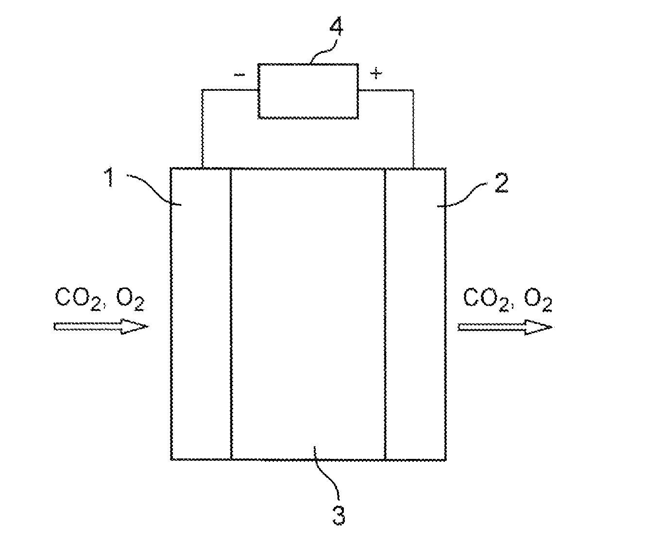
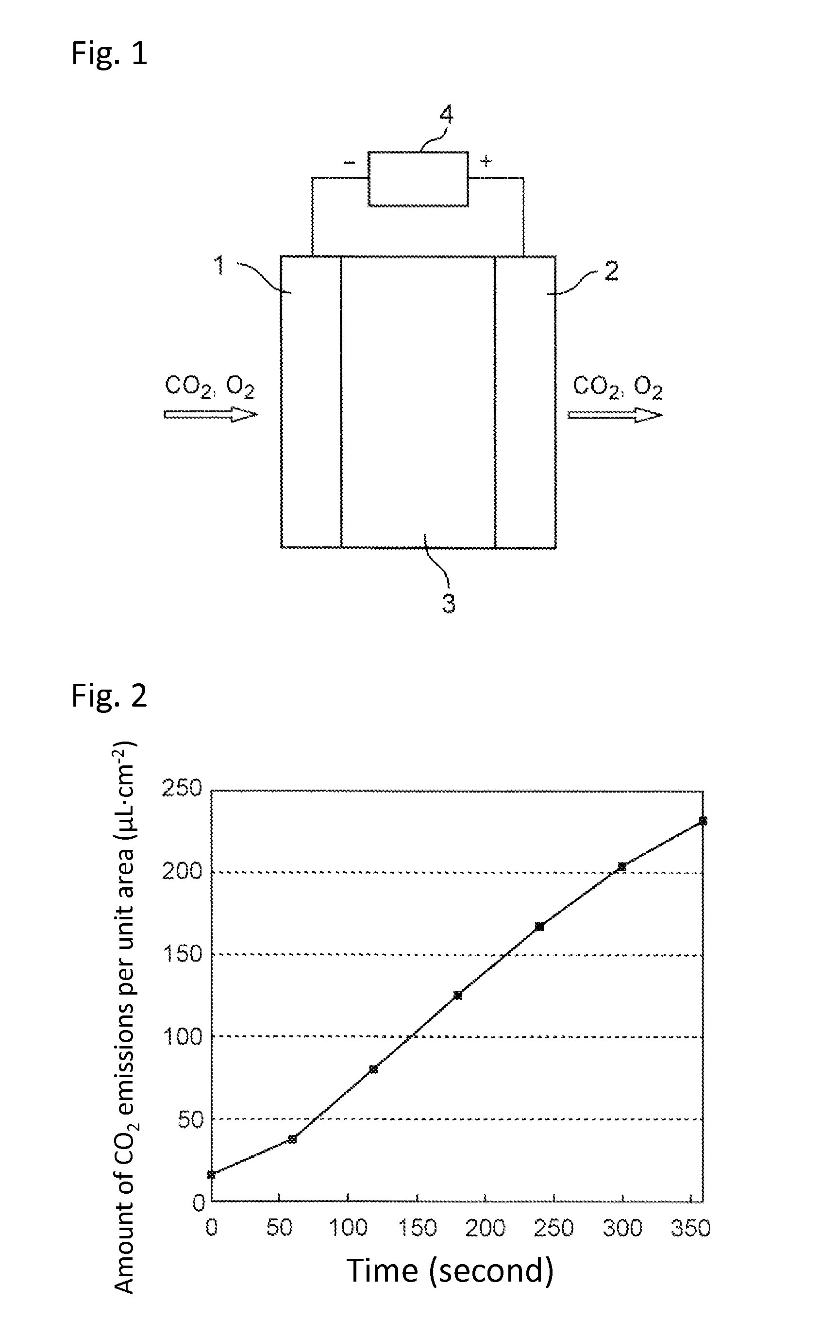
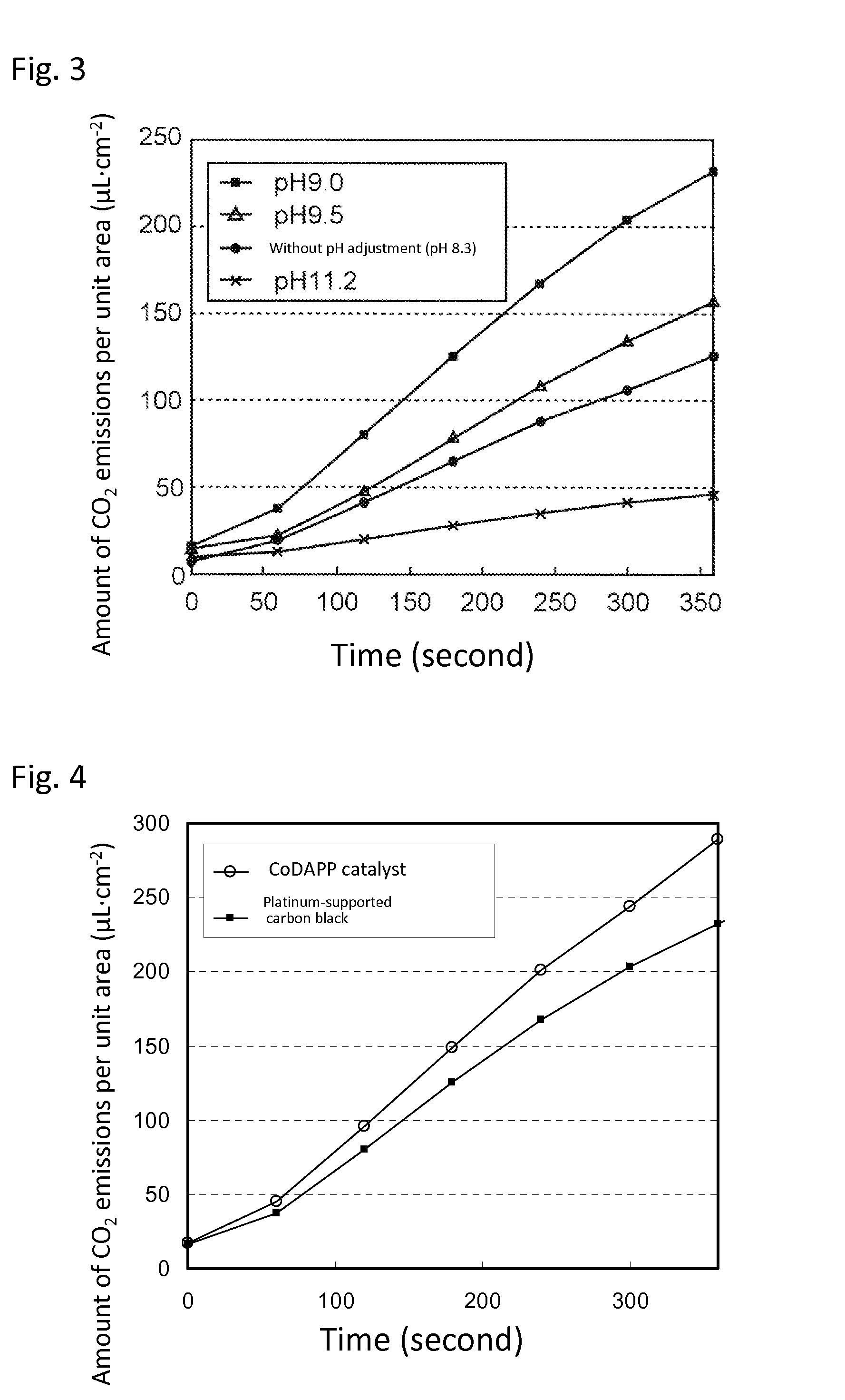
[0078]In the same manner as in Example 1, the pH of the electrolytic solution 3 was variously changed by the addition of NaOH and DC voltage of 1.2 V was applied between the gas diffusion electrode 1 and gas diffusion electrode 2. The amount of carbon dioxide emissions was confirmed by measuring the concentration of carbon dioxide in the glass container attached to the gas diffusion electrode 2 using a carbon dioxide detector. The results are illustrated in FIG. 3. FIG. 3 revealed that the discharge rate of carbon dioxide significantly depends on the pH of the electrolytic solution pH, and that the amount of CO2 emissions per unit area becomes the maximum when the pH of the electrolytic solution is 9.0. As is apparent therefrom, the pH of the electrolytic solution 3 is preferably from 8.5 to 9.5.

example 3

Preparation of Electrode Catalyst (Co-2,6-diaminopyridine Polymer (CoDAP) Catalyst) Made of Metal Complex

[0080]A 2,6-diaminopyridine monomer (Aldrich Corporation) was mixed with an oxidizing agent ammonium peroxydisulfate (APS) (Wako Corporation) in a molar ratio of 1:1.5, followed by mixing. Specifically, 5.45 g of 2,6-diaminopyridine and 1 g of sodium hydroxide were dissolved in 400 mL of distilled water, and then 27.6 g of APS and 100 mL of water were added. The obtained mixture was stirred for 5 minutes and 2,6-diaminopyridine was polymerized at room temperature for 12 hours. After polymerization reaction, the obtained black precipitate was recovered by centrifugation at 3,000 rpm, and then washed three times with distilled water. The precipitate was dried under vacuum at 60° C. for several hours to obtain a 2,6-diaminopyridine polymer.

[0081]Subsequently, 5.45 g of a 2,6-diaminopyridine polymer and 3.62 g of cobalt nitrate (Wako Pure Chemical Industries, Ltd.) were suspended in ...


PUM

PropertyMeasurementUnit
specific surface areaaaaaaaaaaa
pressureaaaaaaaaaa
temperatureaaaaaaaaaa

Abstract

A carbon dioxide enrichment device, comprising:
    • first and second gas diffusion electrodes; and
    • an electrolytic solution existing between them to be in contact with them,
    • wherein the electrolytic solution contains solvent and solute dissolved in it, and the solute is dissolved to form a dissolved inorganic carbon containing carbonic acid, hydrogen carbonate ions, or carbonic acid ions; oxygen is consumed by an oxygen reduction reaction on the first gas diffusion electrode, whereby a dissolved inorganic carbon is formed by a dissolution and ionization reaction of carbon dioxide in the solvent; the dissolved inorganic carbon derived from the solute or the dissolved inorganic carbon is transported to the second gas diffusion electrode; and oxygen is formed from the solvent in the vicinity of the second gas diffusion electrode by an oxidation reaction of the solvent on it, and carbon dioxide is formed from the dissolved inorganic carbon.

Description

TECHNICAL FIELD[0001]The present invention relates to a device capable of enriching carbon dioxide by causing dissolution and release of carbon dioxide in an electrolytic solution utilizing an oxygen-generating / oxygen-reducing electrochemical reaction.BACKGROUND ART[0002]Carbon dioxide is a substance widely distributed on earth, accounting for 0.04% of the atmosphere, which is a compound widely used for industrial applications. Specific examples of industrial use of carbon dioxide include foaming gas for carbonated drinks, bath salts, and fire extinguishing agents; dry ice for cooling; and air for emergency replenishment of automobiles. Carbon dioxide in a supercritical state is also used as an extracting solvent for caffeine, and is further used in a laser that is used in the industrial field, and a carbonic acid gas laser that is used as a medical laser knife. It is also used as a substitute for a chlorofluorocarbon refrigerant in a CO2 refrigerant compressor.[0003]In the agricult...

Claims


Application Information

Patent Timeline
Patent Type & Authority Applications(United States)
IPC IPC(8): C25B11/03C01B32/50C25B3/25
CPCC25B11/035B01D53/229B01D53/326B01D53/62B01D2257/504C01B32/50Y02C20/40Y02P20/10Y02P20/151C25B11/031
Inventor KAMAI, RYOSUZUKA, MICHIONAKANISHI, SHUJIHASHIMOTO, KAZUHITOHELLER, ADAMZHAO, YONG
Owner PANASONIC CORP
Why Eureka
Try Eureka