Method of developing subsurface barriers

Inactive Publication Date: 2014-04-10
GEOSIERRA
View PDF2 Cites 7 Cited by
  • Summary
  • Abstract
  • Description
  • Claims
  • Application Information

AI Technical Summary

Benefits of technology

This patent is about a method and device for creating a barrier in the underground to improve the recovery of oil from oil sand formations using steam and solvents. The invention involves creating multiple vertical inclusions that are filled with a proppant and connected to a first well. Additional vertical inclusions are created at shallower depths to intersect with the first well and with lateral wells. The proppant used is water or hydrocarbon swellable rubber beads, and an alternating direction current is passed through the proppant to heat it and soften the inclusions, which then harden to create a seal. This process creates a secure and impermeable barrier to improve oil recovery.

Problems solved by technology

Unfortunately, the methods currently used for extracting the heavy oil from these formations require the injection of steam under pressure, such as SAGD (Steam Assisted Gravity Drainage), and as such are difficult and often uneconomic if the SAGD well pairs are located in proximity to an outcrop or depleted low pressure steam chambers.
Operating a SAGD steam chamber at lower pressure gives rise to higher steam oil ratios (SORs) but even more significantly at low steam pressures, the steam may not be able to penetrate horizontal shale layers and thus restrict the height of the steam chamber, giving rise to higher SORs and a significant impact on production.
Similar to CSS (Cyclic Steam Stimulation), the SAGD) method has complications, albeit less severe than CSS, due to the lack of steam flow control along the long section of the horizontal well and the difficulty of controlling the growth of the steam chamber.
Thermal recovery processes using steam require large amounts of energy to produce the steam, using either natural gas or heavy fractions of produced synthetic crude.
Burning these fuels generates significant quantities of greenhouse gases, such as carbon dioxide.
Also, the steam process uses considerable quantities of water, which even though may be reprocessed, involves recycling costs and energy use.
The startup phase for the VAPEX process can be lengthy and take many months to develop a controlled connection between the two wells and avoid premature short circuiting between the injector and producer.
The VAPEX process with horizontal wells has similar issues to CSS and SAGD in horizontal wells, due to the lack of solvent flow control along the long horizontal well bore, which can lead to non-uniformity of the vapor chamber development and growth along the horizontal well bore.
The thermal and solvent methods of enhanced oil recovery from oil sands, all suffer from a lack of surface area access to the in place bitumen.
Similarly the VAPEX process is limited by the available surface area to the in place bitumen, because the diffusion process at this contact controls the rate of softening of the bitumen.
Likewise during steam chamber growth in the SAGD process the contact surface area with the in place bitumen is virtually a constant, thus limiting the rate of heating of the bitumen.
ment. The single well systems described above all suffer from low efficiency and high energy loss due to the current passes through a significant distance of the formation from the conductive fracture to the surface g
round. Also the systems with two or more wellbores do not disclosed how the electrode to conductive fracture contact will be other than a point contact resulting in significant energy loss and overheating at such a c
ontact. The above referenced methods describe the use of hydraulic fracturing in its conventional sense, and such application of hydraulic fracturing of brittle rock to form fractures therein are typically not applicable to ductile formations comprising unconsolidated, weakly cemented se
Construction of hydraulic barriers by jet grouting, freezing, sheet piling, etc are common in civil and mining applications but are generally not suitable or economic at depth.
Hydraulic barriers as conformance systems are common in the petroleum field, such as sodium silicate grouts, microbial barriers, swelling particles, etc but are intended for sealing zones around boreholes and not intended for barriers kilometers in length and for the need to be continuous.
Microbial barriers suffer from the disadvantage that they require constant nutrient feeding, but also are only applicable over modest temperature ranges.
Most of the techniques cited are uneconomic due to the extensive number of wells required, others especially those involving hydraulic fracturing, describe the use of hydraulic fracturing in its conventional sense, and such application of hydraulic fracturing of brittle rock to form fractures therein are typically not applicable to ductile formations comprising unconsolidated, weakly cemented sediments.
In brittle formations using conventional hydraulic fracturing, the fracture orientation either vertical or horizontal or inclined, and if vertical its azimuth is controlled by the in-situ formation principal stresses, and as such a continuous vertical barrier along a pre-determined azimuth can not be constructed by conventional hydraulic fracturing, and especially not in weakly cemented formations.
Techniques used in hard, brittle rock to form fractures therein are typically not applicable to ductile formations comprising unconsolidated, weakly cemented sediments.
Apparent cohesion is generally such a small component of strength that it cannot be effectively measured for strong rocks, and only becomes apparent when testing very weakly cemented sediments.
Ductile frictional materials fail under shear stress and consume energy due to frictional sliding, rotation and displacement.
However, such a process has not been duplicated in the laboratory or in shallow field trials.
Linear elastic fracture mechanics is not generally applicable to the behavior of weakly cemented sediments.

Method used


Image

  • Method of developing subsurface barriers
  • Method of developing subsurface barriers
  • Method of developing subsurface barriers

Examples


Embodiment Construction

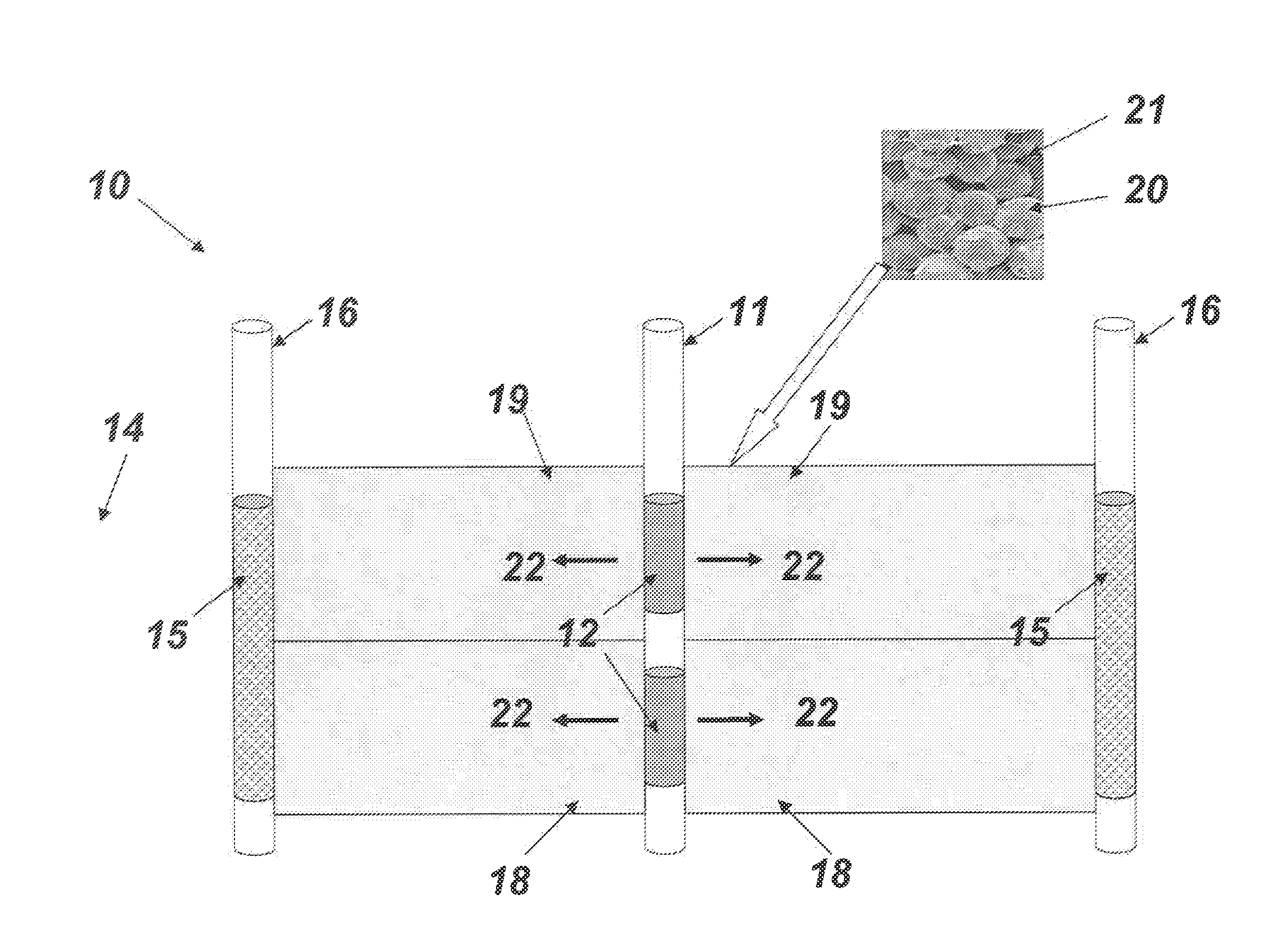
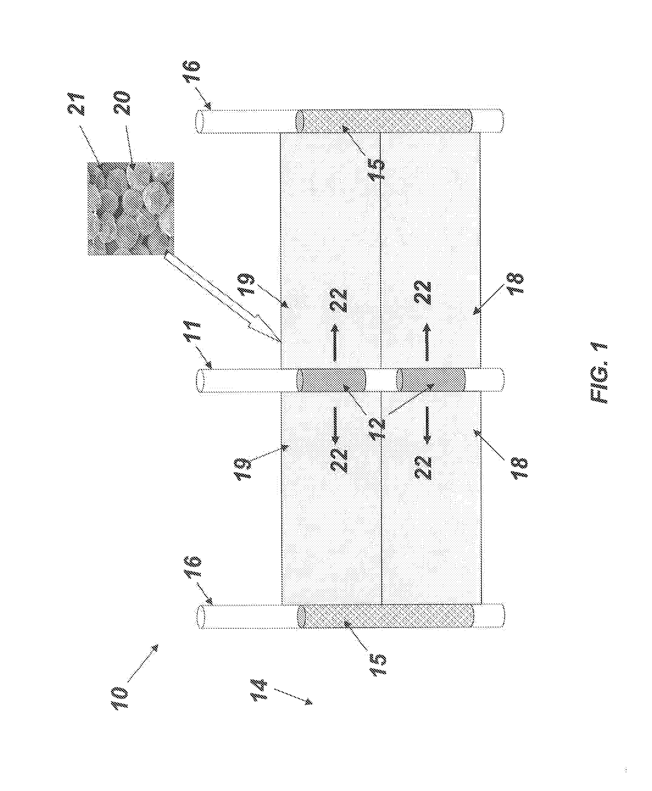
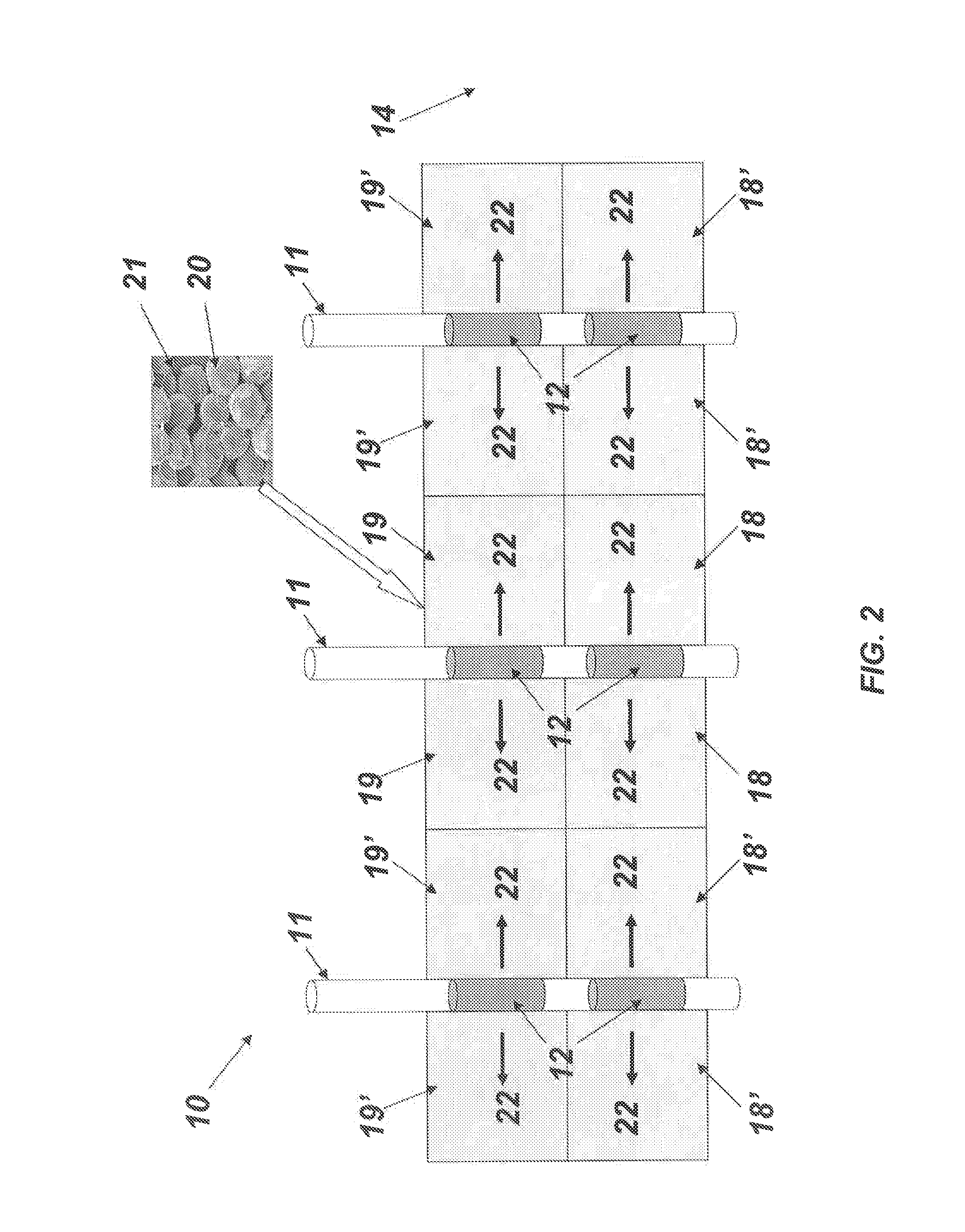
[0038]Several embodiments of the present invention are described below and illustrated in the accompanying drawings. The present invention is a method and apparatus for the construction of a subsurface barrier to enable more efficient, more economical and less environmental impact for the enhanced recovery of petroleum fluids from the subsurface by steam and / or solvents typically using a SAGD recovery system, for the recovery of heavy oil and bitumen in situ from a oil sands formation. Multiple propped vertical inclusions at various azimuths are constructed from multiple wells into the oil sand formation and filled with a proppant. If the proppant is water or hydrocarbon swellable rubber beads, then the beads will swells and fill the void space in the inclusions. If the proppant is a ceramic coated with an electrically conductive resin, then electrodes are placed in the wells, and an alternating current passes through the electrically conductive proppant contained in the inclusions,...


PUM


Abstract

A method and apparatus for construction of a subsurface barrier for the recovery of petroleum fluids from the subsurface by steam and / or solvent injection. Multiple propped vertical inclusions at various azimuths and depths are constructed from multiple wells so that the inclusions intersect and coalesce. The inclusions are made impermeable by a variety of means including the proppant swelling to fill the voids of the inclusions. The proppant includes ceramic beads coated with an electrically conductive and heat hardenable resin. The resin is electrically heated and flows to fill the voids in the inclusions as the resin hardens. The proppant includes sand or ceramic beads that are subject to cold saline water circulated between the wells to freeze the formation pore water. The proppant includes low viscosity grout that is injected with a time delay setting agent or electrically conductive grout that is heated and set by electric current passing through the grout.

Description

TECHNICAL FIELD[0001]The present invention generally relates to enhanced recovery of petroleum fluids from the subsurface by steam injection, in which a nearby outcrop or depleted steam chamber causes loss of steam from the active process zone or requires reducing the steam pressure in the active process zone to minimize water loss. A barrier between the process zone and the outcrop or depleted chamber, enables the enhanced recovery process to be more efficient, more economical, minimizes water usage and results in increased production of petroleum fluids from the subsurface formation.BACKGROUND OF THE INVENTION[0002]Heavy oil and bitumen oil sands are abundant in reservoirs in many parts of the world such as those in Alberta, Canada, Utah and California in the United States, the Orinoco Belt of Venezuela, Indonesia, China and Russia. The hydrocarbon reserves of the oil sand deposit is extremely large in the trillions of barrels, with recoverable reserves estimated by current techno...

Claims


Application Information

Patent Timeline
IPC IPC(8): E21B33/13E21B43/24
CPCE21B43/2401E21B33/13E21B43/2406E21B43/267
Inventor HOCKING, GRANT
Owner GEOSIERRA
Why Eureka
Try Eureka