
Engagement position storage device and brake system including the same

Active Publication Date: 2014-04-03
HITACHI ASTEMO LTD
View PDF3 Cites 7 Cited by
  • Summary
  • Abstract
  • Description
  • Claims
  • Application Information

AI Technical Summary

Benefits of technology

The engagement position storage device stores the position of the clutch when the vehicle is in a certain state after acceleration in the front-back direction. This helps to detect the position of the clutch accurately and smoothly starting the vehicle. The device is particularly useful when starting a vehicle with a new clutch.

Problems solved by technology

This technique, however, has a problem of, for automatic release of the parking brake in response to the confirmed starting operation such as activation of an accelerator pedal by a driver, especially for rapid starting of a vehicle equipped with a manual transmission, it takes time to remove a braking force completely after starting of the releasing of the parking brake, and so it has difficulty to release the parking brake completely at a sufficient speed necessary for smooth starting of the vehicle.
The acceleration of a vehicle, however, may change due to factors other than the starting of the vehicle by a clutch engagement operation, such as vibrations induced internally or externally of the vehicle or inclination of the road surface.
As such, the technique disclosed in Patent Document 2 may erroneously determine, as a clutch engagement position, the clutch position where acceleration changes due to a factor other than the starting of the vehicle by a clutch engagement operation, and so fail to detect the clutch engagement position of the vehicle finely.
Automatic releasing of the braking force based on such a clutch engagement position performed at a position immediately before the clutch engagement position may erroneously release the braking force at a position away from the actual clutch engagement position, thus failing in smooth starting of the vehicle.

Method used

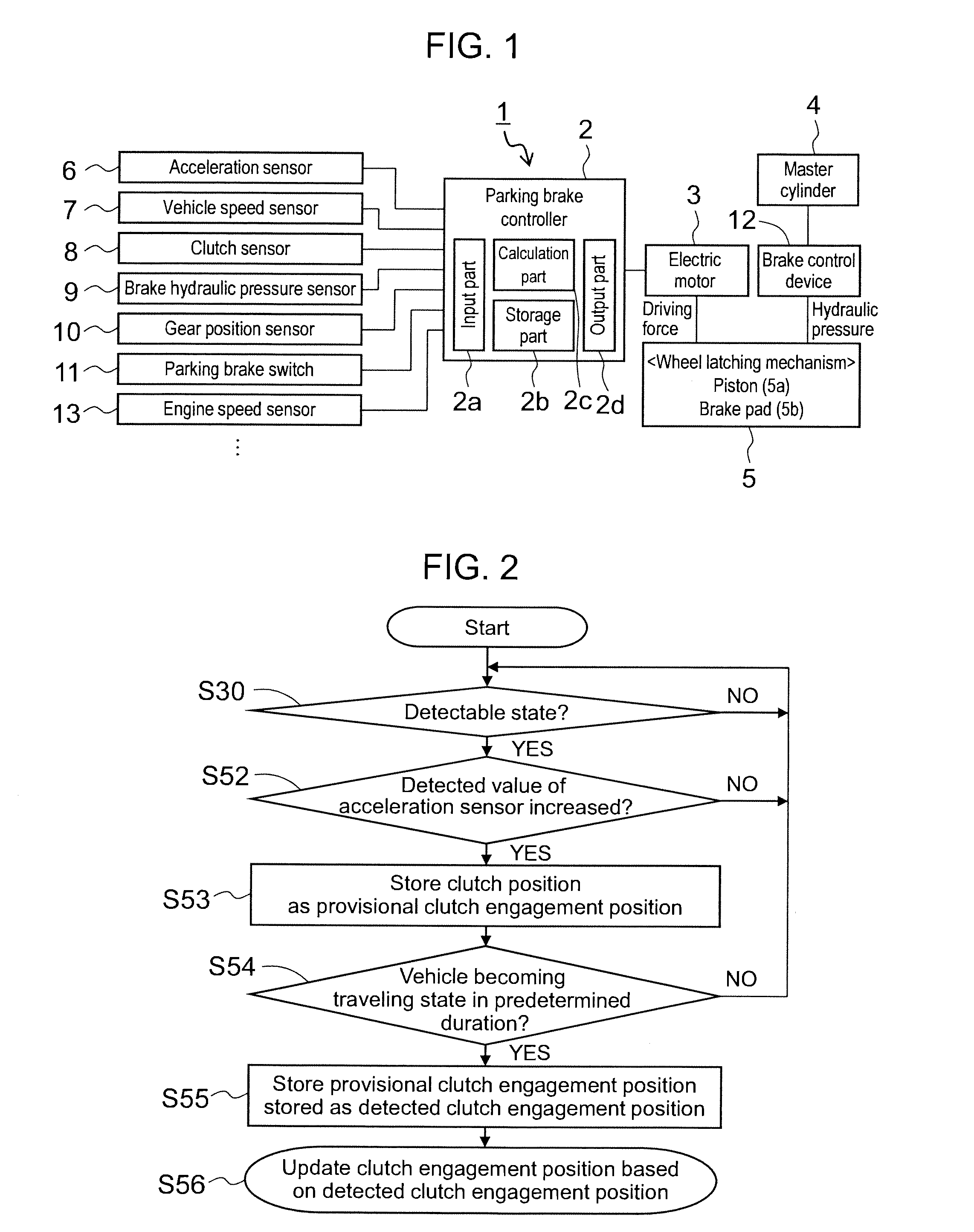
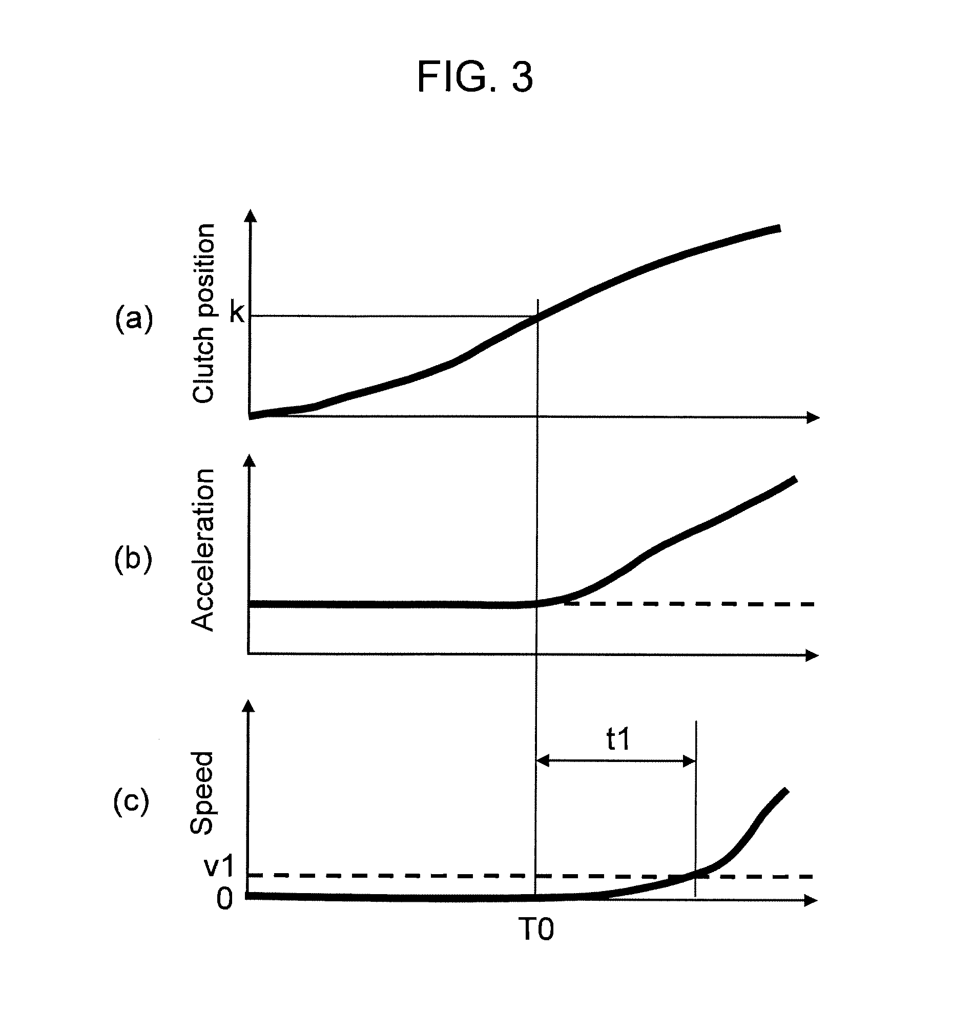

Image

  • Engagement position storage device and brake system including the same
  • Engagement position storage device and brake system including the same
  • Engagement position storage device and brake system including the same

Examples


Embodiment Construction

[0023]The following describes embodiments of an engagement position storage device according to the present invention and a brake system including the same, with reference to the drawings.

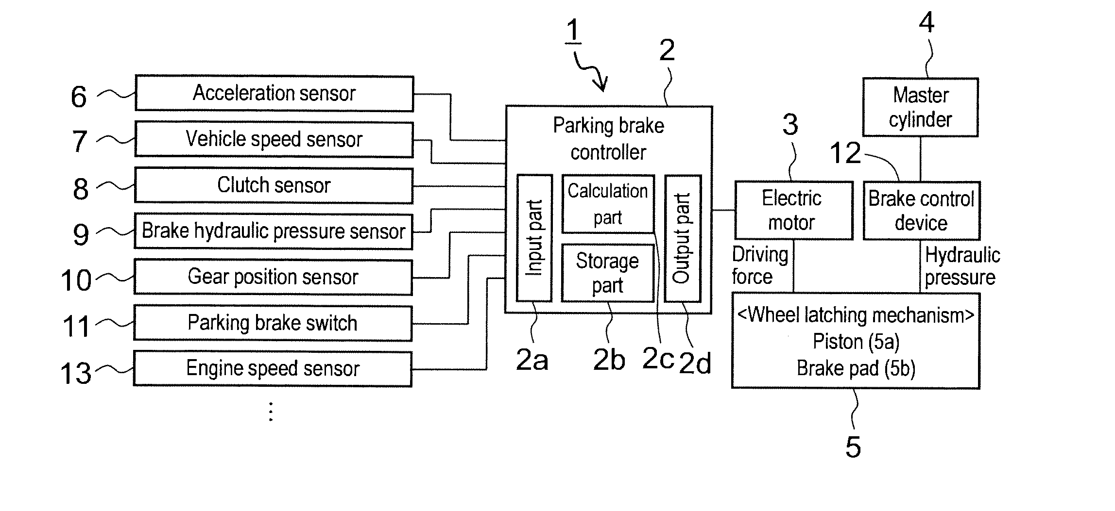
[0024]FIG. 1 shows a basic configuration of a brake system including an engagement position storage device according to the present invention.

[0025]A brake system 1 shown in the drawing mainly includes: a master cylinder (driving device) 4, an electric motor (driving device) 3 for parking brake; a wheel latching mechanism 5 that is activated by wheel cylinder hydraulic pressure (e.g., hydraulic pressure controlled by hydraulic pressure generated by the master cylinder 4) or by the driving force of the electric motor 3; and a parking brake controller (control device) 2 that controls the driving by the electric motor 3, thus controlling the activation of the wheel latching mechanism 5 The brake system 1 may include a brake control device 12 to control hydraulic pressure by the master cylinder 4. When...


PUM


Abstract

Provided is an engagement position storage device capable of detecting a clutch engagement position of a vehicle finely and a brake system including such a device. In an engagement position storage device 2b that stores an engagement position of a clutch to engage and disengage power of a vehicle, when the vehicle becomes a traveling state in predetermined duration after acceleration in a front-back direction of the vehicle changes, the engagement position storage device 2b stores a clutch engagement position based on a clutch position detected when the acceleration changes. A brake system 1 includes a wheel latching mechanism 5 that latches wheels of a vehicle by driving a propelling member 5a by driving devices 3 and 4; and a controller 2 that controls driving of the propelling member 5a of the wheel latching mechanism 5 based on a clutch engagement position stored in the engagement position storage device 2b.

Description

BACKGROUND OF THE INVENTION[0001]1. Field of the Invention[0002]The present invention relates to an engagement position storage device that stores an engagement position of a clutch, and a brake system including the same.[0003]2. Background Art[0004]Conventionally known hydraulic disk brakes to be installed in a vehicle such as an automobile include a disk brake equipped with a parking brake mechanism.[0005]Such a disk brake for use as a usual brake propels a piston in a cylinder by hydraulic pressure and presses a brake pad against a disk rotor, thus generating a braking force. For use as a parking brake, the disk brake rotates a rotating member of a ball-and-ramp mechanism (rotation-linear motion conversion mechanism) by an electric motor via a reducing mechanism to linearly move a linear motion member and move a piston forward, and so press a brake pad against a disk rotor, thus generating a braking force.[0006]Such a hydraulic disk brake equipped with a parking brake mechanism h...

Claims


Application Information

Patent Timeline
IPC IPC(8): G07C5/08
CPCG07C5/0841B60T7/12B60T2201/06B60W10/00B60W2510/02F16D48/062F16D48/08F16D2500/10412F16D2500/3026F16D2500/3067F16D2500/3109F16D2500/3112F16D2500/3115F16D2500/3127F16D2500/7041F16D2500/70414F16D48/06F16D48/10F16D55/224F16D65/18
Inventor SETO, SHINJIKANAI, MASAKIYOKOYAMA, WATARU
Owner HITACHI ASTEMO LTD
Learn More