
Transmission-geometry electrochemical cell for in-situ scattering and spectroscopy investigations

a technology of electrochemical cells and transmission-geometry, which is applied in the field of xray and neutron scattering experimentation devices, can solve the problems of limited means for characterizing nanostructured materials, unrealistic operating conditions of samples, and inability to achieve real-time data collection, etc., to achieve the effect of improving data reliability, continuous measurement of cell reactivity, and reducing tim

Active Publication Date: 2014-04-03
UCHICAGO ARGONNE LLC
View PDF5 Cites 48 Cited by
  • Summary
  • Abstract
  • Description
  • Claims
  • Application Information

AI Technical Summary

Benefits of technology

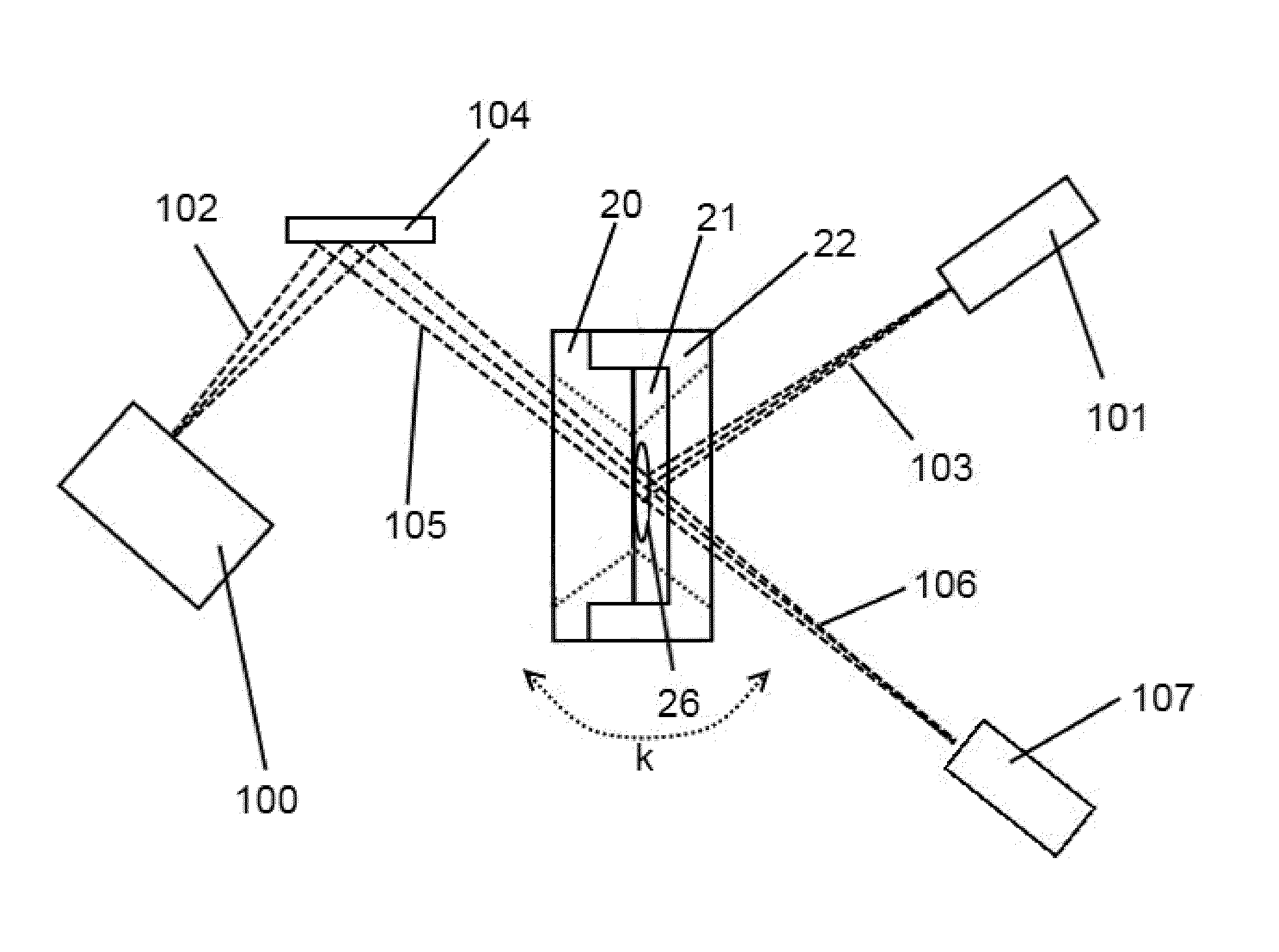
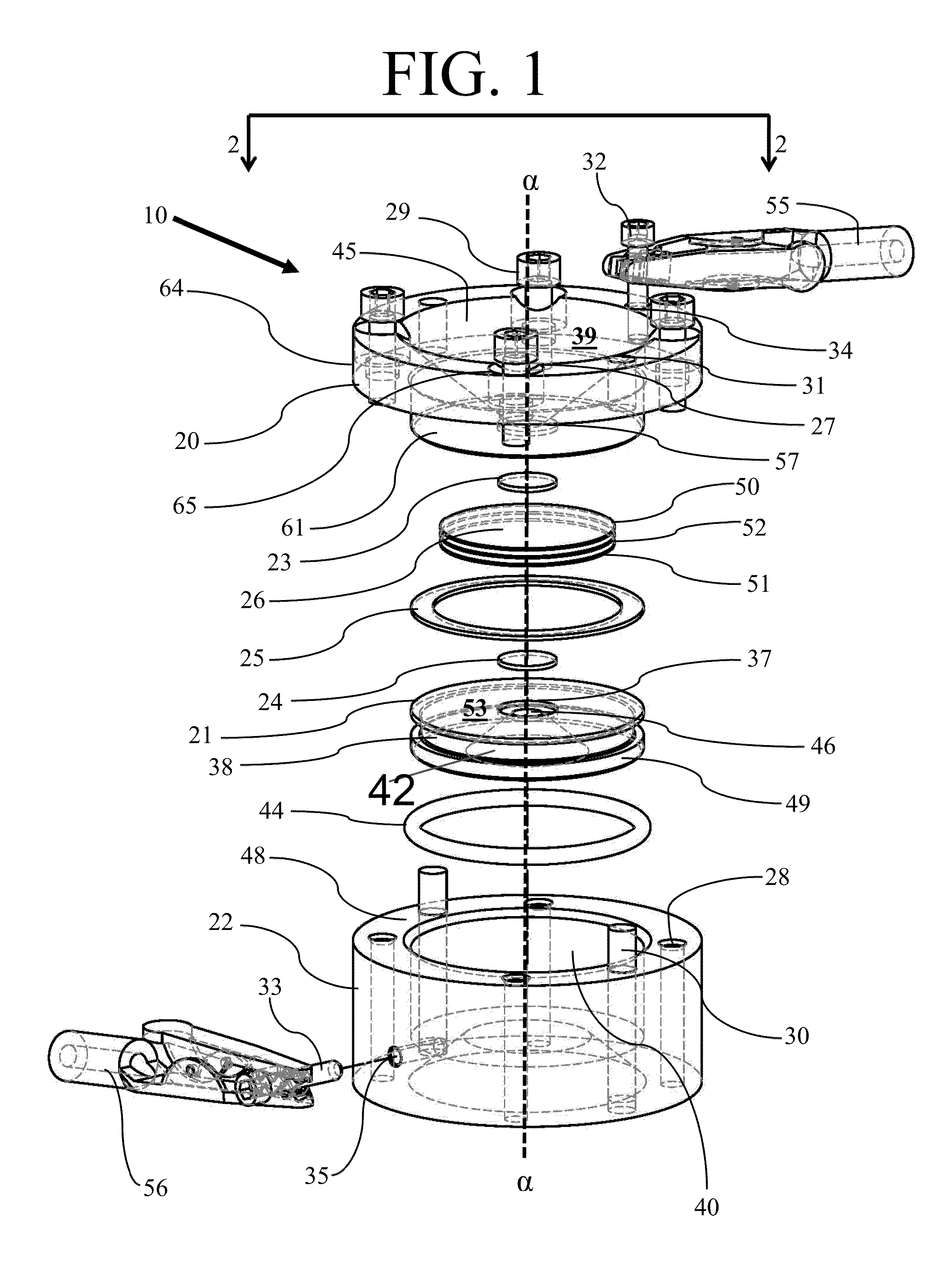
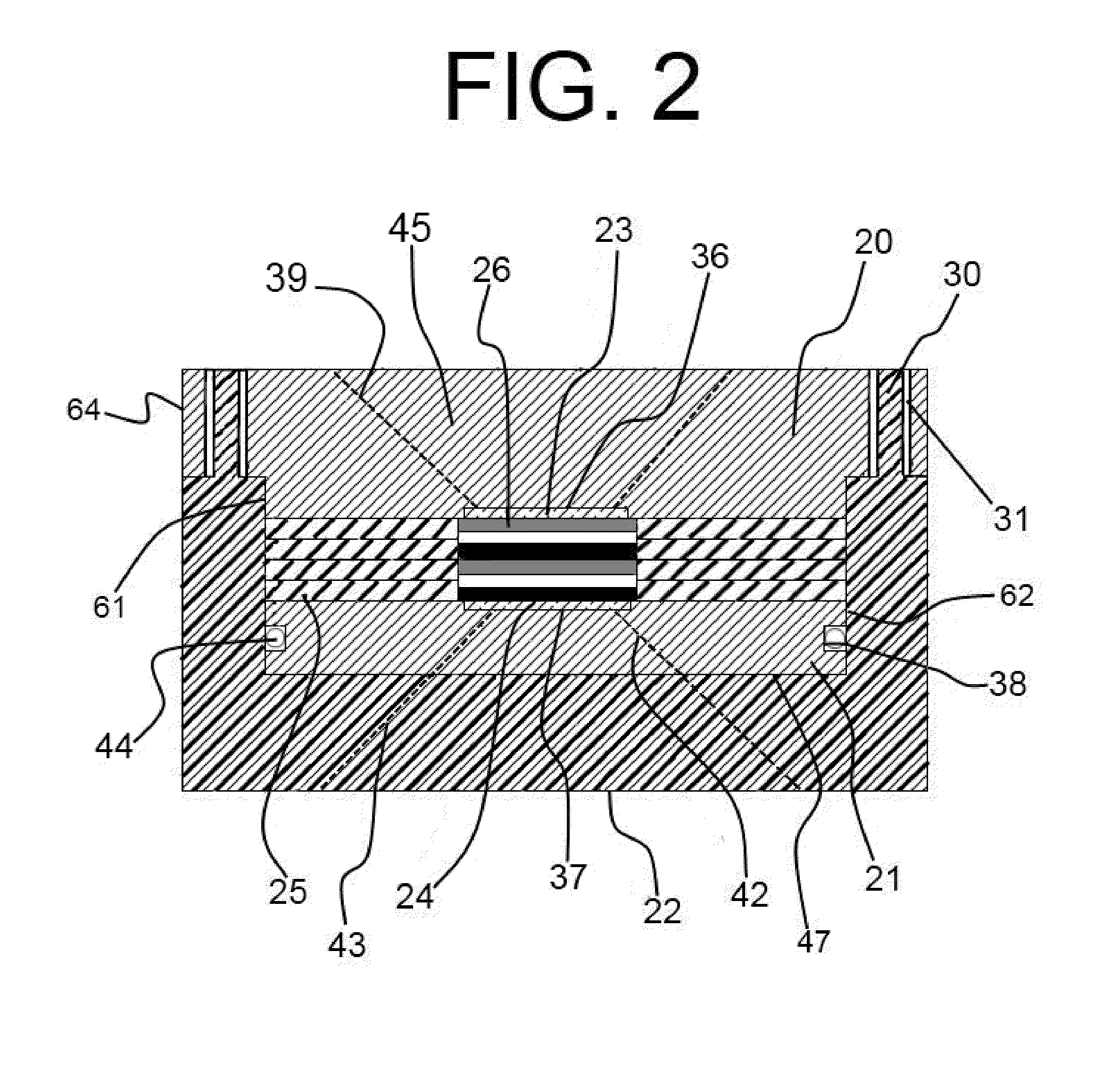
The present invention provides a system for characterizing the performance of an electrochemical battery by using X-ray imaging during the cycling process. The system allows for multiple X-ray characterizations to be performed using a single sample, which can be monitored without disassembling the sample. The device includes a reaction cell with wide-angle X-ray entrance and exit apertures, and a sample holding internal chamber that can collect data necessary for PDF measurements without the need for disassembling the sample. Additionally, the device can collect data in real-time, continuously measuring the reactivity of the cell while it is exposed to radiation such as X-rays. The invention reduces the time needed for micro- and nano-structure characterizations of an electrochemical cell and enables the continuous, unbroken collection of data of reactions occurring in an electrochemical cell during substantially its entire discharge and charge cycles. The sample holder is designed to isolate the cell from the ambient environment and allows for accurate monitoring of the cell's electrical performance and electrode structure throughout the electrochemical cycle.

Problems solved by technology

Many other forms of scattering, spectroscopy and imaging require involved sample preparation or a high vacuum environment, which create unrealistic operating conditions for the sample.
These techniques have been applied in the field of battery technology, but with limited results.
This has proven to be the limiting step, and the problem is compounded by the variability introduced through the use of successive samples instead of a single one.
This is problematic as battery technology has become increasingly important in recent years, with the emphasis on green technologies, electric vehicles, and reducing dependence on foreign oil.
A means for characterizing nanostructured materials is currently lacking
But, state of the art sample holders only allow battery components to be investigated over a single or, rarely, a second electrochemical cycle.
State-of-the-art ex-situ analysis fails to address this need.
Typical ex-situ characterization techniques have several disadvantages: (1) they are extremely labor intensive because each cell requires disassembly to recover the electrode materials and each disassembly runs the risk of “short circuiting” the cell; (2) they require different samples to be studied at different points in the electrochemical cycle, so direct comparison of data is difficult; (3) in practice, ex situ techniques only allow a limited number of points in the cycle to be studied; and (4) they inhibit the investigation of highly-reactive, short-lived intermediaries because the delay involved in recovering the samples during disassembly of the testing device allows such intermediaries to decompose or react before the sample can be characterized.
State-of-the-art designs use flexible thin film windows, such as polyimide, aluminized Mylar, and “coffee bags,” to transmit X-rays, which lead to inconsistent battery stack pressure.
The flexibility of these materials creates a bulge over the center of the battery, causing a disparity in reaction rates between the center and outer regions of the battery where the stack pressure is maintained.
Therefore, the area of the battery probed by the X-ray beam produces misleading and unrepresentative information about the reaction and structural changes.
Thus, the battery components deteriorate faster, limiting the number of possible cycles.
Conversely, rigid windows integrated with existing sample holder technologies allow for only limited data collection.
These are only compatible with a limited range of X-ray methodologies.

Method used


Image

  • Transmission-geometry electrochemical cell for in-situ scattering and spectroscopy investigations
  • Transmission-geometry electrochemical cell for in-situ scattering and spectroscopy investigations
  • Transmission-geometry electrochemical cell for in-situ scattering and spectroscopy investigations

Examples


Embodiment Construction

[0037]The foregoing summary, as well as the following detailed description of certain embodiments of the present invention, will be better understood when read in conjunction with the appended drawings. As used herein, an element or step recited in the singular and preceded with the word “a” or “an” should be understood as not excluding plural said elements or steps, unless such exclusion is explicitly stated. Furthermore, references to “one embodiment” of the present invention are not intended to be interpreted as excluding the existence of additional embodiments that also incorporate the recited features. Moreover, unless explicitly stated to the contrary, embodiments “comprising” or “having” an element or a plurality of elements having a particular property may include additional such elements not having that property.

[0038]Battery technology continues to represent a major force in energy production, transport and storage. The inner workings of advanced batteries remain a mystery...


PUM


Abstract

The present invention relates to a test chamber that can be used to perform a variety of X-ray and neutron spectroscopy experiments including powder diffraction, small-angle scattering, X-ray absorption spectroscopy, and pair distribution functions, such chamber comprising a first electrode with an X-ray transparent window; a second electrode with an X-ray transparent window; a plurality of insulating gaskets providing a hermetic seal around the sample and preventing contact between said first and second electrodes; and an insulating housing into which the first electrode is secured.

Description

CONTRACTUAL ORIGIN OF THE INVENTION[0001]The United States Government has rights in this invention pursuant to Contract No DE-AC02-06CH11357 between the United States Government and UChicago Argonne, LLC representing Argonne National Laboratory.BACKGROUND OF THE INVENTION[0002]1. Field of the Invention[0003]The present invention relates to X-ray and neutron scattering experimentation devices, and more specifically, the present invention relates to an in-situ test chamber for an electrochemical cell.[0004]2. Background of the Invention[0005]X-ray and neutron scattering and spectroscopy techniques are common in many fields of science, especially those where the characterization of a micro- or nano-structured material is required.[0006]There are a wide variety of X-ray scattering and spectroscopy techniques available to glean important information about a sample's structure. Spectroscopies and scattering methods are favored because they allow nondestructive testing of samples and inexp...

Claims


Application Information

Patent Timeline
IPC IPC(8): G01N23/00H01M2/10
CPCH01M10/48G01N2223/307G01N23/20025Y02E60/10
Inventor CHUPAS, PETER J.CHAPMAN, KARENA W.KURTZ, CHARLES A..BORKIEWICZ, OLAF J.WIADEREK, KAMILA MAGDELENASHYAM, BADRI
Owner UCHICAGO ARGONNE LLC
Learn More