
Control apparatus for rotary electric machine, rotary electric machine drive system, and control method for rotary electric machine

a control apparatus and electric machine technology, applied in the direction of electric generator control, dynamo-electric converter control, dynamo-electric gear control, etc., can solve the problems of increasing the viscosity of coolant, the demagnetization of permanent magnets is dependent, etc., to prevent the demagnetization of permanent magnets and improve energy efficiency

Inactive Publication Date: 2014-02-27
TOYOTA JIDOSHA KK
View PDF8 Cites 17 Cited by
  • Summary
  • Abstract
  • Description
  • Claims
  • Application Information

AI Technical Summary

Benefits of technology

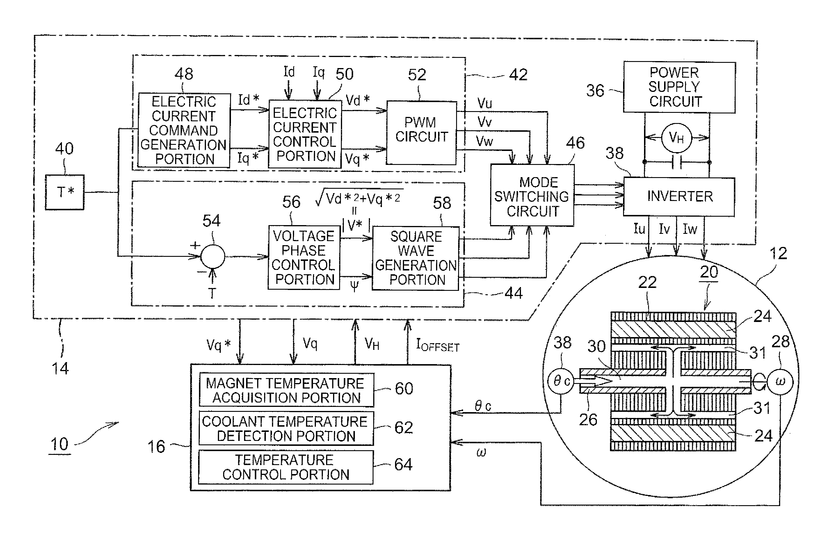
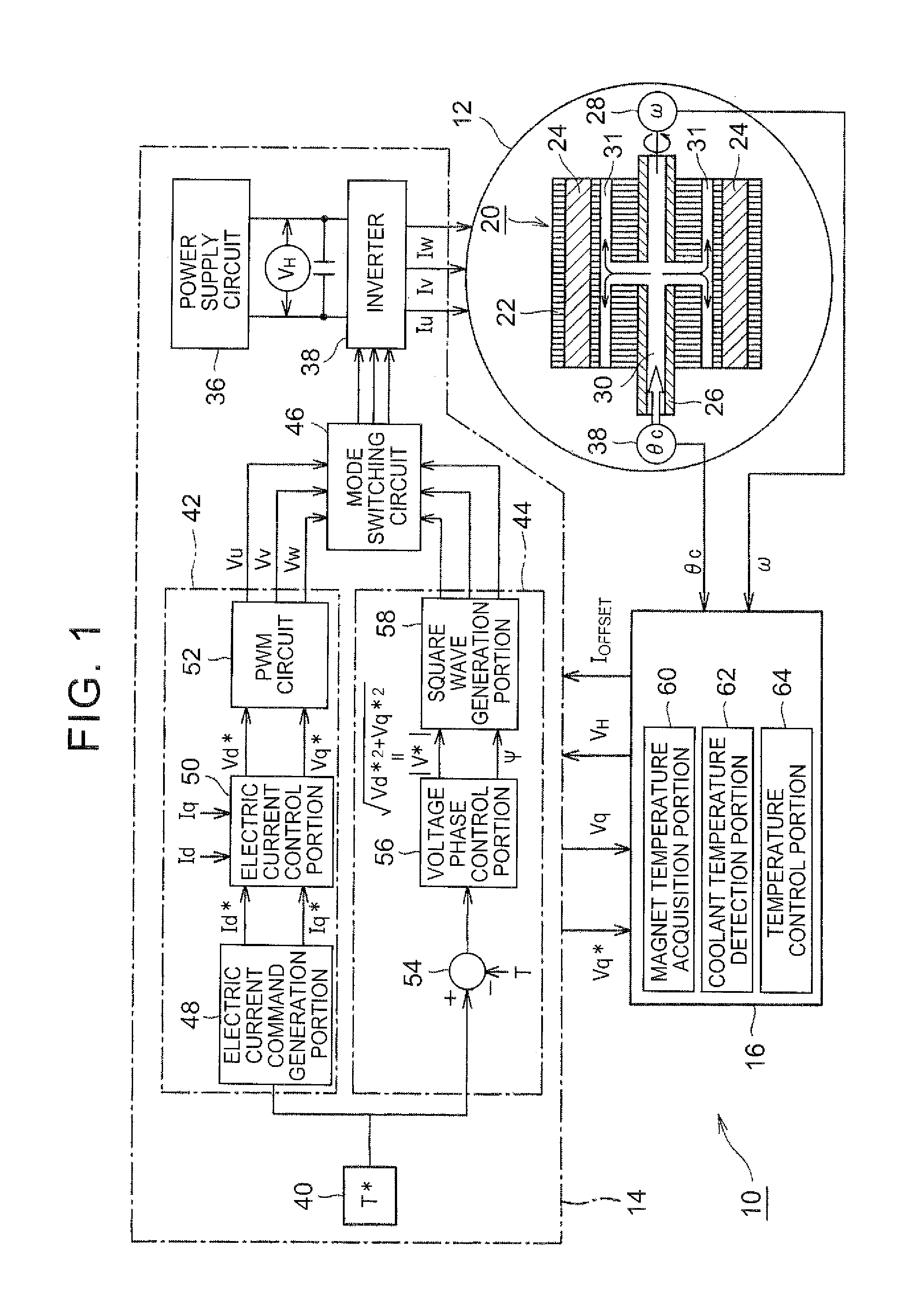
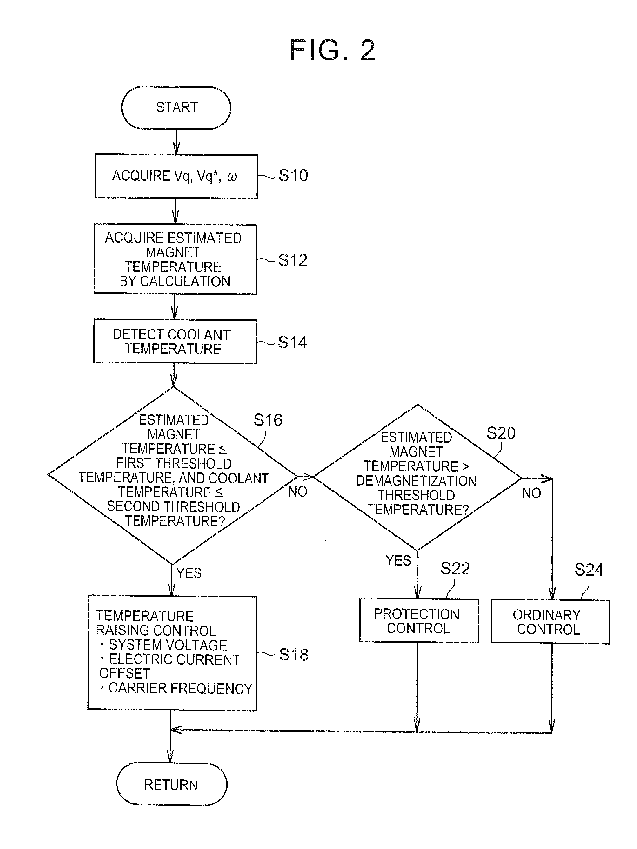
The invention describes a control system for a rotary electric machine that prevents demagnetization of the permanent magnet while improving energy efficiency. By setting a threshold temperature for the permanent magnet, the system raises the temperature of the coolant and decreases its viscosity, which reduces energy loss. The control system also utilizes a sine wave control mode or a square wave control mode to improve energy efficiency, depending on the magnetic field fluctuation of the stationary element. Additionally, the system controls the drive currents of the three phases to prevent offset deviation and reduce eddy current loss, which further improves energy efficiency. The system can also quickly raise the temperature of the permanent magnet and coolant without changing the operation of the machine.

Problems solved by technology

In rotary electric machines that use permanent magnets, there is a problem of demagnetization of permanent magnets dependent on change in temperature.
On the other hand, lowering the temperature of the coolant causes an increase of viscosity of the coolant.

Method used


Image

  • Control apparatus for rotary electric machine, rotary electric machine drive system, and control method for rotary electric machine
  • Control apparatus for rotary electric machine, rotary electric machine drive system, and control method for rotary electric machine
  • Control apparatus for rotary electric machine, rotary electric machine drive system, and control method for rotary electric machine

Examples


Embodiment Construction

[0031]Embodiments of the invention will be described in detail hereinafter with reference to the drawings. Although a motor-generator to be mounted in a vehicle will be described below as a rotary electric machine, the rotary electric machine in the invention may be a rotary electric machine that is not mounted in a vehicle. Furthermore, although neodymium magnets will be described as permanent magnets employed in the rotary electric machine below, the permanent magnets may also be other rare earth magnets, for example, samarium-cobalt base magnets, samarium-iron-nitrogen base magnets, etc. Furthermore, besides rare earth magnets, the permanent magnets may also be ferrite magnets or alnico magnets. Although in the following description, the coolant for cooling the rotor that includes permanent magnets is an automatic transmission fluid (ATF), the coolant may also be an oil coolant other than ATF, and may also be an aqueous coolant or a gaseous coolant.

[0032]Although the following de...


PUM


Abstract

A control apparatus for a rotary electric machine, which has a rotary element that includes a permanent magnet, includes a magnet temperature acquisition portion, a coolant temperature detection portion and a temperature control portion. The magnet temperature acquisition portion acquires information about temperature of the permanent magnet. The coolant temperature detection portion detects temperature of a coolant that cools at least the rotary element. The temperature control portion performs a temperature raising control of the permanent magnet when the temperature of the permanent magnet is less than or equal to a first threshold temperature and the temperature of the coolant is less than or equal to a second threshold temperature.

Description

[0001]INCORPORATION BY REFERENCE[0002]The disclosure of Japanese Patent Application No. 2012-186527 filed on Aug. 27, 2012 including the specification, drawings and abstract is incorporated herein by reference in its entirety.BACKGROUND OF THE INVENTION[0003]1. Field of the Invention[0004]The invention relates to a control apparatus for a rotary electric machine, a rotary electric machine drive system, and a control method for a rotary electric machine.[0005]2. Description of Related Art[0006]In rotary electric machines that use permanent magnets, there is a problem of demagnetization of permanent magnets dependent on change in temperature. For example, Japanese Patent Application Publication No. 2009-171640 (JP 2009-171640 A) discloses a drive control apparatus for an electric motor which estimates the temperature of the permanent magnets attached to the rotary element from the oil temperature or the stator temperature and then changes the ranges of application of drive control mod...

Claims


Application Information

Patent Timeline
IPC IPC(8): H02K9/19H02P21/00H02P21/22H02P27/04H02P27/06H02P27/08
CPCH02K9/19H02P29/662
Inventor HIRAI, YUMIYATA, KAZUHIDE
Owner TOYOTA JIDOSHA KK
Learn More