Systems for and methods of fusing a sacroiliac joint
- Summary
- Abstract
- Description
- Claims
- Application Information
AI Technical Summary
Benefits of technology
Problems solved by technology
Method used
Image
Examples
first embodiment
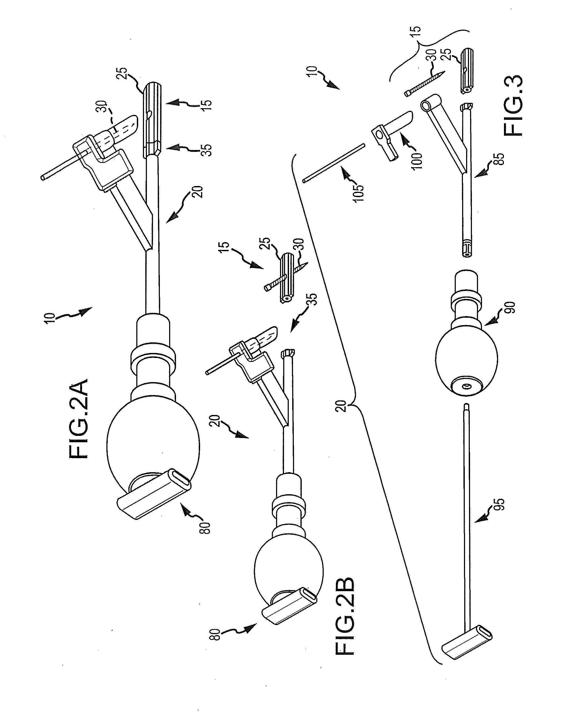
[0196]To begin a detailed discussion of the system 10, reference is made to FIGS. 2A-3. FIG. 2A is an isometric view of the system 10. FIG. 2B is the same view as FIG. 2A, except an implant assembly 15 of the system 10 is separated from a delivery tool 20 of the system 10. FIG. 3 is the same view as FIG. 2A, except the system 10 is shown exploded to better illustrate the components of the system 10.
[0197]As can be understood from FIGS. 2A and 2B, the system 10 includes a delivery tool 20 and an implant assembly 15 for implanting at the sacroiliac joint via the delivery tool 20, the implant assembly 15 being for fusing the sacroiliac joint. As indicated in FIG. 3, the implant assembly 15 includes an implant 25 and an anchor element 30 (e.g., a bone screw or other elongated body). As discussed below in greater detail, during the implantation of the implant assembly 15 at the sacroiliac joint, the implant 25 and anchor element 30 are supported by a distal end 35 of the delivery tool 20...
second embodiment
[0256]To begin a detailed discussion of the system 10, reference is made to FIGS. 32-33. FIG. 32 is an isometric view of the system 10, and FIG. 33 is the same view as FIG. 32, except the system 10 is shown exploded to better illustrate the components of the system 10.
[0257]As can be understood from FIGS. 32 and 33, the system 10 includes a delivery tool 20 and an implant assembly 15 for implanting at the sacroiliac joint via the delivery tool 20, the implant assembly 15 being for fusing the sacroiliac joint. As indicated in FIG. 33, the implant assembly 15 includes an implant 25 and an anchor element 30 (e.g., a bone screw or other elongated body). In one embodiment, the implant assembly 15 is the same as that described above with respect to FIGS. 4-17. As discussed below in greater detail, during the implantation of the implant assembly 15 at the sacroiliac joint, the implant 25 and anchor element 30 are supported by a distal end 35 of the delivery tool 20, as illustrated in FIG. ...
third embodiment
[0271]To begin a detailed discussion of the system 10, reference is made to FIGS. 37-40. FIGS. 37 and 38 are different isometric views of the system 10. FIG. 39 is the same view as FIG. 37, except the system 10 is shown exploded to better illustrate the components of the system 10. FIG. 40 is a side elevation of the system wherein the tool is attached to the implant assembly for delivery of the implant assembly to the sacroiliac joint.
[0272]As can be understood from FIGS. 37-40, the system 10 includes a delivery tool 20 and an implant assembly 15 for implanting at the sacroiliac joint via the delivery tool 20, the implant assembly 15 being for fusing the sacroiliac joint. As indicated in FIG. 39, the implant assembly 15 includes an implant 25 and an anchor element 30 (e.g., a bone screw or other elongated body).
[0273]As can be understood from a comparison of FIGS. 2A-3 to FIGS. 37-40, the delivery tool 20 of FIGS. 2A-3 is the same as the delivery tool 20 of FIGS. 37-40. Thus, for a ...
PUM
 Abstract
Description
Claims
Application Information
 - R&D
- Intellectual Property
- Life Sciences
- Materials
- Tech Scout
- Unparalleled Data Quality
- Higher Quality Content
- 60% Fewer Hallucinations
Browse by: Latest US Patents, China's latest patents, Technical Efficacy Thesaurus, Application Domain, Technology Topic, Popular Technical Reports.
© 2025 PatSnap. All rights reserved.Legal|Privacy policy|Modern Slavery Act Transparency Statement|Sitemap|About US| Contact US: help@patsnap.com


