Eureka AIR delivers breakthrough ideas for toughest innovation challenges, trusted by R&D personnel around the world.

Solvent-free process based graphene electrode for energy storage devices

a technology of energy storage devices and solvent-free processes, applied in the direction of non-metal conductors, cell components, conductors, etc., can solve the problems of high specific surface area (ssa) of graphene sheets, and high specific energy per unit volume of electrode materials. , to achieve the effect of high charge storage capacitance or lithium storage capacity, high specific energy per unit volume, and high specific surface area

Pending Publication Date: 2014-01-30
GLOBAL GRAPHENE GRP INC
View PDF13 Cites 228 Cited by
  • Summary
  • Abstract
  • Description
  • Claims
  • Application Information

AI Technical Summary

Benefits of technology

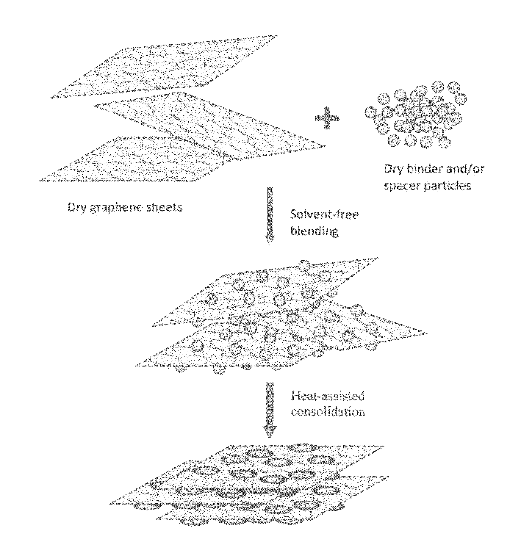
The present invention provides a method for making a durable, high-yield, and inorganic-free electrode for use in energy storage devices. The electrode is made by mixing dry graphene sheets with binder and / or spacer particles and compacting them into a film. This method allows for a higher proportion of active material in the electrode and eliminates the need for solvents or processing aids. The electrode can be used in batteries or supercapacitors and exhibits high charge storage capacity or lithium storage capacity. The invention also provides a cost-effective and efficient way to make a high-yield energy storage device.

Problems solved by technology

When the graphene electrodes were fabricated by the known slurry casting or coating methods (the wet methods), several unexpected major difficulties or challenges were encountered:(1) The specific surface area (SSA) of graphene sheets is dramatically curtailed by the slurry casting / coating process.
This is very unfortunate because the specific capacitance of a supercapacitor and the specific capacity of a lithium battery electrode are all directly proportional to the SSA of a graphene-based electrode.(2) The slurry casting / coating processes for graphene electrodes are unexpectedly found to be much more difficult to conduct than for other types of electrode materials (e.g. graphite, Si, and lithium iron phosphate for a lithium-ion cell, and AC for a supercapacitor).
This implies that the specific capacity and specific energy per unit volume of electrode material is very low and, hence, the resulting battery will occupy a huge volume given the same desired battery weight or battery energy density.
This is a serious drawback when the battery pack volume or space is limited (e.g. in the trunk of an electric vehicle).(4) When a conventional wet coating / casting method is used for graphene electrode preparation, the bonding quality between graphene particles and the substrate (e.g. a current collector) is very poor.
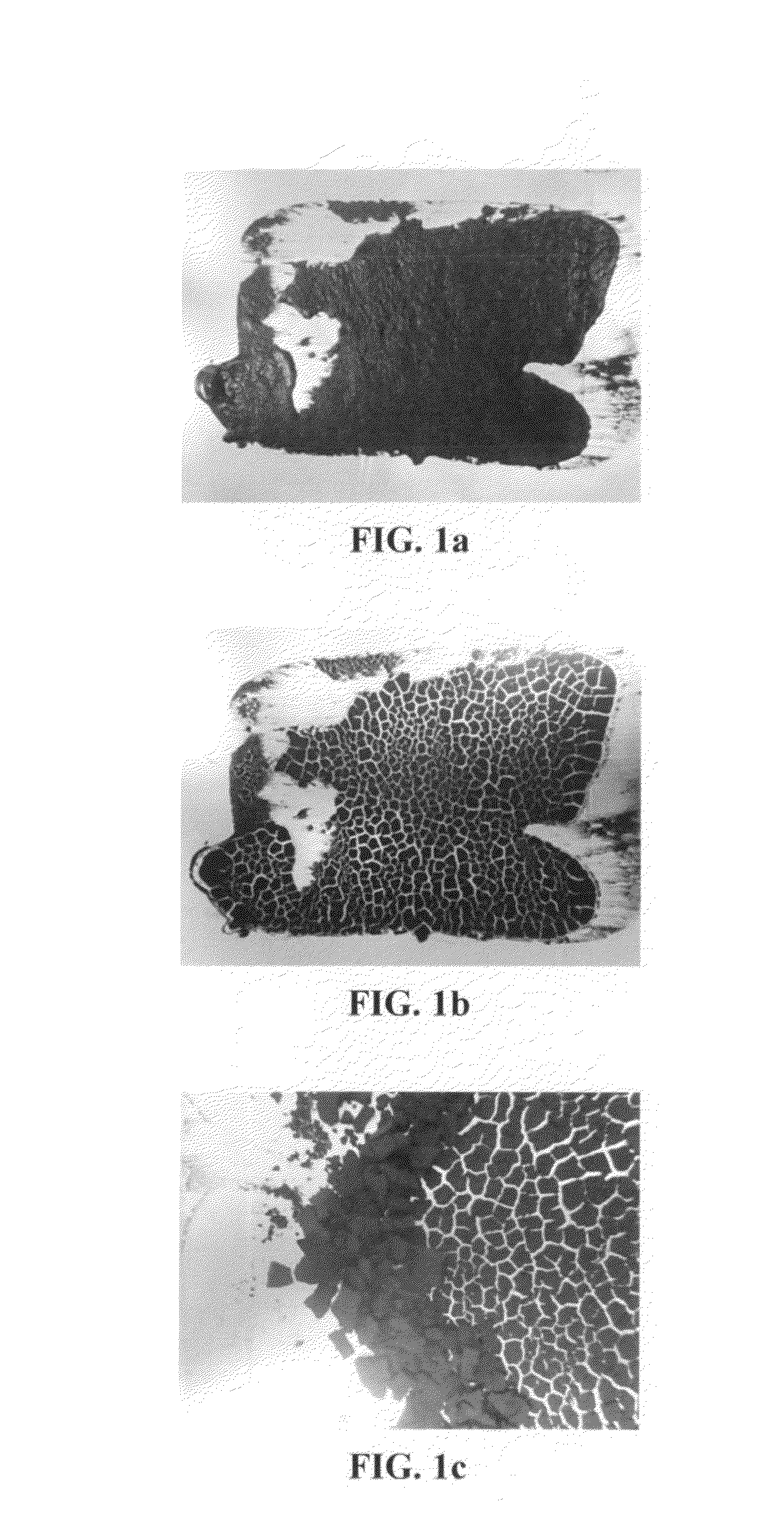
As can be seen in FIG. 1(c), the cracked pieces of graphene electrode film can be easily peeled off from the aluminum foil substrate.(5) When the conventional wet-coating method is utilized for the graphene electrode preparation, the coating quality is very poor possibly due to the necessarily low binder content in the slurry.
These requirements demand an unusually high binder content, which significantly reduces the relative proportion of an electrode active material (since the binder is not capable of storing charges).
However, as the binder loading increases, the binder will cover most of the surface of graphene particles, thereby significantly decreasing the effective specific surface area of the electrode that can be in ionic contact with the electrolyte.
The internal resistance increase will reduce the power density and output voltage, as well as produce more heat inside the cell during a battery operation.(8) Despite the high specific capacity and high specific energy density have been achieved for graphene-based electrodes, most of these electrodes contain a small amount of the active material because of the difficulty to cast a thicker layer of graphene powder to the current collector.
The low areal density of electrode materials on current collector is no problems when they are used for concept verification in preliminary studies, but it is a very serious drawback for a real commercial energy storage cell.
There has been no prior art method available or suggested for overcoming the aforementioned eight problems, separately or in combination.
These residual impurities were thought to otherwise result in poorer cycle performance of a supercapacitor.
The gas also needs to be applied at a dew point below −40° F. The fibrillizing process requires large amounts of high pressure gas and it is quite energy consuming.
These requirements are not conducive to mass production of the electrode materials.

Method used


Image

  • Solvent-free process based graphene electrode for energy storage devices
  • Solvent-free process based graphene electrode for energy storage devices
  • Solvent-free process based graphene electrode for energy storage devices

Examples


example 1

Preparation of Nano Graphene Platelets (NGPs)

[0112]Chopped graphite fibers with an average diameter of 12 μm was used as a starting material, which was immersed in a mixture of concentrated sulfuric acid, nitric acid, and potassium permanganate (as the chemical intercalate and oxidizer) to prepare graphite intercalation compounds (GICs). The fiber segments were first dried in a vacuum oven for 24 h at 80° C. Then, a mixture of concentrated sulfuric acid, fuming nitric acid, and potassium permanganate (at a weight ratio of 4:1:0.05) was slowly added, under appropriate cooling and stirring, to a three-neck flask containing fiber segments. After 48 hours of reaction, the acid-treated graphite fibers were filtered and washed thoroughly with deionized water until the pH level of the solution reached 4. After being dried at 100° C. overnight, the resulting graphite intercalation compound (GIC) was subjected to a thermal shock at 1050° C. for 45 seconds in a tube furnace to form exfoliated...

example 2

Preparation of Single-Layer Graphene from Meso-Carbon Micro-Beads (MCMBs)

[0113]Meso-carbon microbeads (MCMBs) were supplied from China Steel Chemical Co. This material has a density of about 2.24 g / cm3 with a median particle size of about 16 μm. MCMB (10 grams) were intercalated with an acid solution (sulfuric acid, nitric acid, and potassium permanganate at a ratio of 4:1:0.05) for 72 hours. Upon completion of the reaction, the mixture was poured into deionized water and filtered. The intercalated MCMBs were repeatedly washed in a 5% solution of HCl to remove most of the sulphate ions. The sample was then washed repeatedly with deionized water until the pH of the filtrate was neutral. The slurry was dried and stored in a vacuum oven at 60° C. for 24 hours. The dried powder sample was placed in a quartz tube and inserted into a horizontal tube furnace pre-set at a desired temperature, 1,080° C. for 45 seconds to obtain a graphene material. TEM and atomic force microscopic studies in...

example 3

Preparation of Pristine Graphene

[0114]In a typical procedure, five grams of graphite flakes, ground to approximately 20 μm or less in sizes, were dispersed in 1,000 mL of deionized water (containing 0.1% by weight of a dispersing agent, Zonyl® FSO from DuPont) to obtain a suspension. An ultrasonic energy level of 85 W (Branson 5450 Ultrasonicator) was used for exfoliation, separation, and size reduction of graphene sheets for a period of 15 minutes to 2 hours.


PUM

PropertyMeasurementUnit
specific surface areaaaaaaaaaaa

Abstract

Disclosed is an electrode for an electrochemical energy storage device, the electrode comprising a self-supporting layer of a mixture of graphene sheets and spacer particles and / or binder particles, wherein the electrode is prepared without using water, solvent, or liquid chemical. The graphene electrode prepared by the solvent-free process exhibits many desirable features and advantages as compared to the corresponding electrode prepared by a known wet process. These advantages include a higher electrode specific surface area, higher energy storage capacity, improved or higher packing density or tap density, lower amount of binder required, lower internal electrode resistance, more consistent and uniform dispersion of graphene sheets and binder, reduction or elimination of undesirable effect of electrolyte oxidation or decomposition due to the presence of water, solvent, or chemical, etc.

Description

FIELD OF THE INVENTION[0001]The present invention relates generally to the field of energy storage devices. More particularly, the present invention relates to electrode structures and solvent-free methods for making graphene-based dry electrode structures in batteries and supercapacitors.BACKGROUND OF THE INVENTION[0002]The references listed below are cited in the discussion of the background:[0003]1. B. Z. Jang and W. C. Huang, “Nano-scaled Graphene Plates,” U.S. patent application Ser. No. 10 / 274,473 (10 / 21 / 2002); now U.S. Pat. No. 7,071,258 (07 / 04 / 2006).[0004]2. Lulu Song, A. Zhamu, Jiusheng Guo, and B. Z. Jang “Nano-scaled Graphene Plate[0005]Nanocomposites for Supercapacitor Electrodes” U.S. patent application Ser. No. 11 / 499,861 (08 / 07 / 2006); now U.S. Pat. No. 7,623,340 (Nov. 24, 2009).[0006]3. A. Zhamu and B. Z. Jang, “Process for Producing Nano-scaled Graphene Platelet Nanocomposite Electrodes for Supercapacitors,” U.S. patent application Ser. No. 11 / 906,786 (Oct. 4, 2007);...

Claims


Application Information

Patent Timeline
Patent Type & Authority Applications(United States)
IPC IPC(8): H01G9/00H01M4/64H01B1/04H01B1/12H01M4/66B82Y30/00H01B1/02H01M4/583H01M4/62
CPCH01B1/04B82Y30/00B82Y40/00H01G11/32H01G11/36H01M4/0402H01M4/366H01M4/587H01M10/0525H01M10/054Y02E60/13Y02E60/10
Inventor WANG, MINGCHAOCHEN, GUORONGZHAMU, ARUNAJANG, BOR Z.
Owner GLOBAL GRAPHENE GRP INC
Why Eureka
Eureka Blog
Learn More