
Multi-hop reflector sessions

a multi-hop reflector and reflector technology, applied in the field of multi-hop reflector sessions, can solve the problems of inability to generate a test pdu from an originator, inability to accommodate round-trip or two-way measurements, delay in user information transmission,

Active Publication Date: 2014-01-30
ACCEDIAN NETWORKS
View PDF8 Cites 60 Cited by
  • Summary
  • Abstract
  • Description
  • Claims
  • Application Information

AI Technical Summary

Benefits of technology

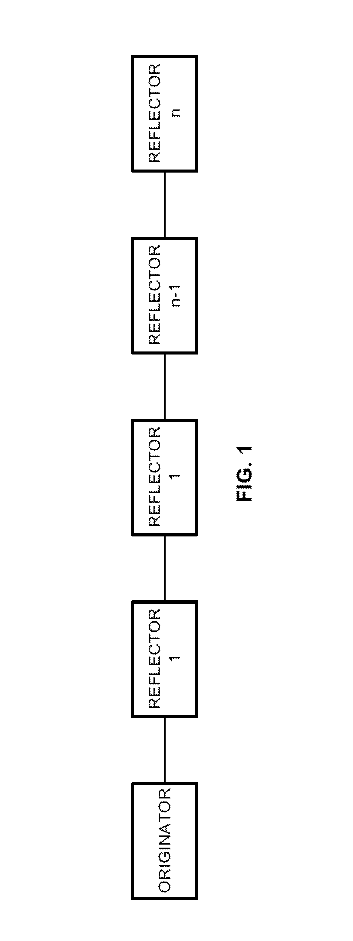
The patent describes a method for measuring and reporting performance parameters in a network using test protocol data units generated at the originator and relayed by multiple reflectors along a test path. The test protocol data units include timestamps that identify the times when the data unit departs from the originator and reaches each reflector in both the upstream and downstream directions. The reflectors are configured with addressing information of the next reflector and use it to relay the test protocol data unit to the next reflector. The technical effect is the ability to accurately measure and report performance parameters in a network using a reliable and efficient method.

Problems solved by technology

However, it does not accommodate round-trip or two-way measurements.
Due to the need to explicitly generate different OAM sessions (one per pair of Originator and Reflector) in the current state of the art, it is not possible to generate a Test PDU from an Originator that can collect measurements from more than one Reflector at a time along a test path, even though the Test PDU may traverse said Reflectors in order to reach a remote Reflector.
Unfortunately, two of the drawbacks of TCP are added delay in the transmission of user information, and the possible limitation of maximum advertised window size and interaction with the bandwidth-delay product and flow control interaction with loss and delay of the Ethernet Service.
This creates challenges to efficiently measure delays and packet loss with traditional methods.

Method used


Image

  • Multi-hop reflector sessions
  • Multi-hop reflector sessions
  • Multi-hop reflector sessions

Examples


Embodiment Construction

[0040]Although the invention will be described in connection with certain preferred embodiments, it will be understood that the invention is not limited to those particular embodiments. On the contrary, the invention is intended to cover all alternatives, modifications, and equivalent arrangements as may be included within the spirit and scope of the invention as defined by the appended claims.

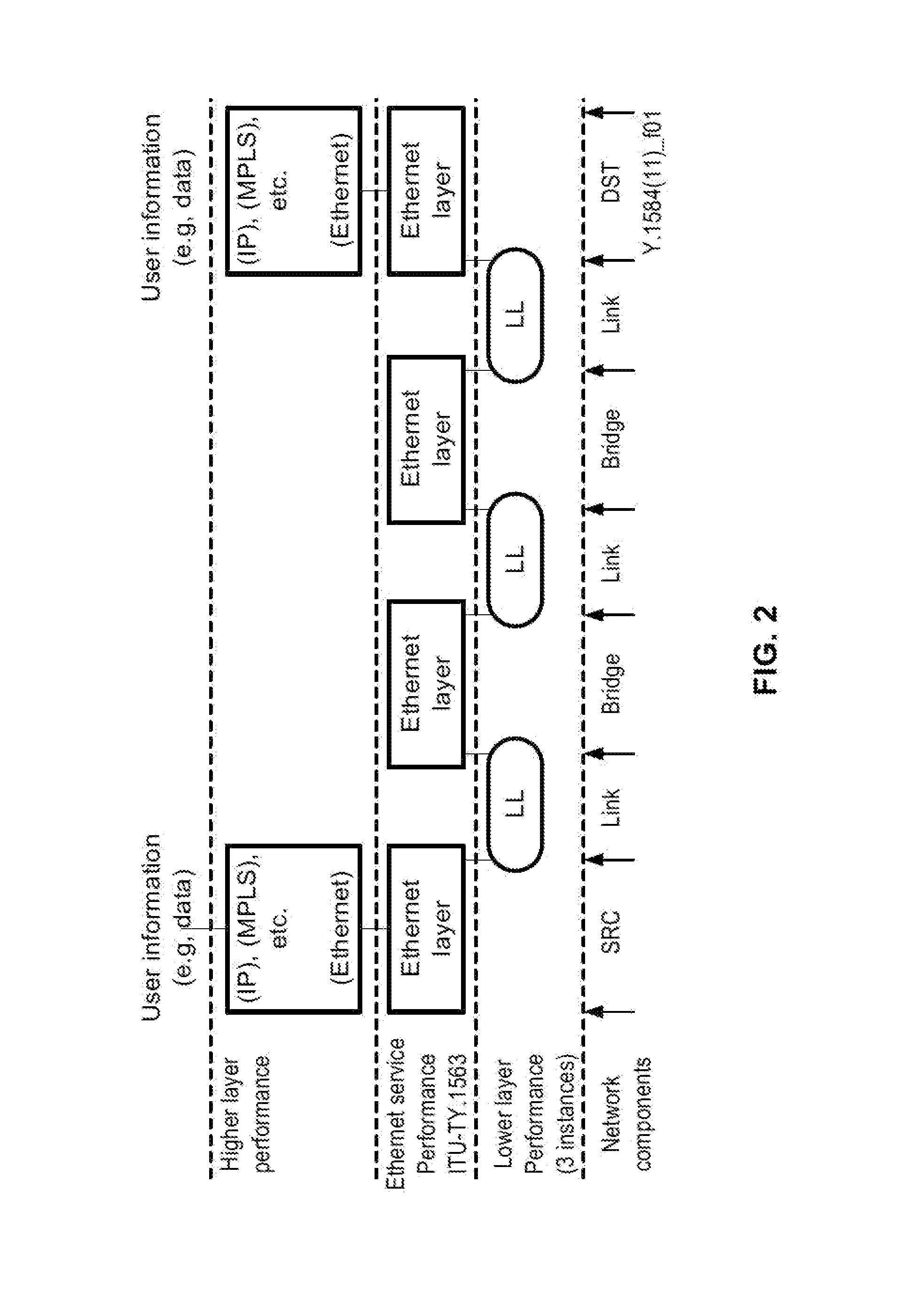
[0041]The embodiment operates in the context of the need for a framework that allows for performance measurements as defined in standards such as ITU-T Y.1731, IETF RFC 5357 (TWAMP) and IEEE 802.1ag. These standards all rely on the notion of an Originator (or Session-Sender) that generates test traffic toward a Reflector (or Session-Reflector), where 2-way measurements require that the Reflector returns (or reflects) the test traffic toward the Originator.

[0042]These standards allow efficient delay and packet loss measurements via a bi-directional measurement function, i.e. 2×OneWay, for switc...


PUM


Abstract

A method for measuring and reporting performance parameters in a network having at least one originator for generating test protocol data units, and multiple reflectors for relaying the test protocol data units along successive segments of a test path in the network. The method generates the test protocol data units at the originator and transmits the test protocol data unit along a test path that includes multiple reflectors. Each reflector relays the test protocol data unit to the next reflector along the test path. Measurements of performance parameters are collected from the multiple reflectors in the test protocol data unit by inserting timestamps into the test protocol data unit at the originator and each of the reflectors to identify the departure and arrival times for each test protocol data unit at the originator and each of the reflectors in both the downstream and upstream directions along the test path.

Description

CROSS-REFERENCE TO RELATED APPLICATIONS[0001]This application incorporates by reference in its entirety the following application, which has the same filing date as the present application: “Automatic Setup of Reflector Instances,” by Hansson, Hagsand and Wallman, Attorney Docket No. 268665-000025USPT.FIELD OF THE INVENTION[0002]Multi-hop Reflector Sessions in the context of an Ethernet Operations Administration and Maintenance (OAM) framework.BACKGROUND OF THE INVENTION[0003]For many years, Ethernet has been used as a LAN (Local Area Network) technology, and enterprises have managed these networks with the use of Internet protocols such as Simple Network Management Protocol (SNMP), ICMP Echo (or IP Ping), IP Traceroute, and Cisco Unidirectional Link Detection Protocol (UDLD). EOAM (Ethernet Operations Administration and Maintenance) is a set of protocols for installing, monitoring, and troubleshooting MANs (Metropolitan Area Network) and WANs (Wide Area network). The use of Etherne...

Claims


Application Information

Patent Timeline
Patent Type & Authority Applications(United States)
IPC IPC(8): H04W24/00
CPCH04L43/106H04L43/12H04L43/50H04L43/0864
Inventor NYDELL, HENRIK
Owner ACCEDIAN NETWORKS
Learn More