
Vacuum Truck With Pneumatic Transfer System

a technology of pneumatic transfer and vacuum truck, which is applied in the direction of load transportation vehicle, conveyor, transportation items, etc., can solve the problems of significant volume loss of revert fines by air entrainment and dissipation, significant portion of such materials may become entrained and subsequently become airborne, and entrained revert materials from conventional sources to achieve the effect of minimizing re-entrainment or escap

Inactive Publication Date: 2014-01-16
BM METALS SERVICES
View PDF5 Cites 27 Cited by
  • Summary
  • Abstract
  • Description
  • Claims
  • Application Information

AI Technical Summary

Benefits of technology

The present invention is a vacuum truck designed to collect, transport, and discharge waste materials with finely powdered or dusty particles. The invention minimizes the re-entrainment or escape of these particles into the atmosphere during collection and discharge.

Problems solved by technology

While conventional vacuum truck designs have proven suitable for use in the collection of municipal waste, litter and the like, heretofore such apparatus have presented various difficulties in the collection, transportation and recycling or reuse of spillage and / or waste mining or ore processing revert material.
The use of conventional vacuum trucks in the collection of such revert materials frequently results in the loss of significant volumes of revert fines by air entrainment and dissipation.
In particular, as the storage tank is opened to the atmosphere and emptied, significant portion of such materials may become entrained and subsequently become air borne, escaping via the storage tank access doors, discharge auger outlets and the like.
In addition to a loss of commercially valuable material from recycling process streams, the escape of entrained revert materials from conventional vacuum trucks may present environmental concerns, particularly where such trucks are used in enclosed or confined spaces, such as within underground mine operations, or inside steel processing or industrial facilities.

Method used


Image

  • Vacuum Truck With Pneumatic Transfer System
  • Vacuum Truck With Pneumatic Transfer System
  • Vacuum Truck With Pneumatic Transfer System

Examples


Embodiment Construction

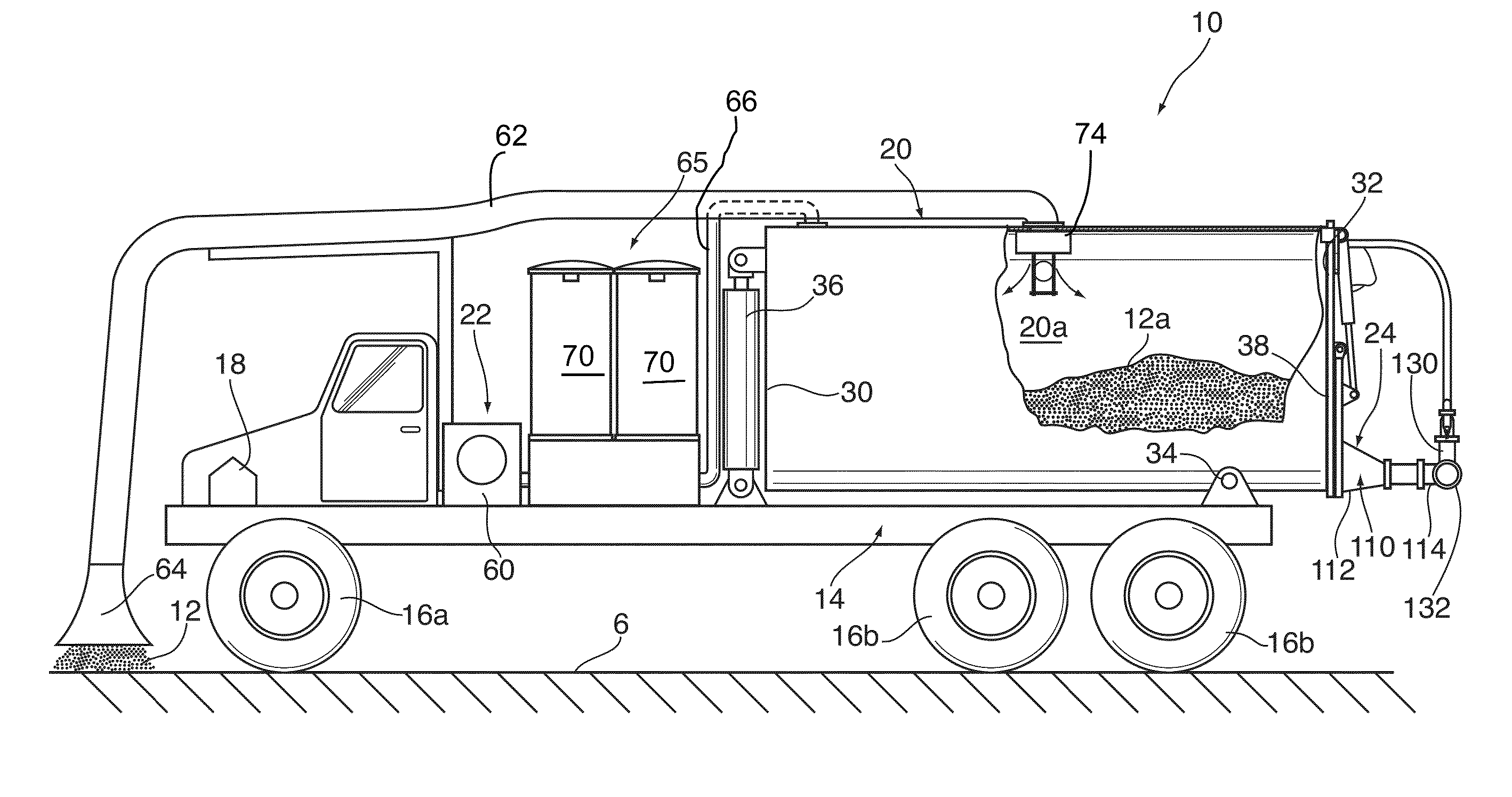
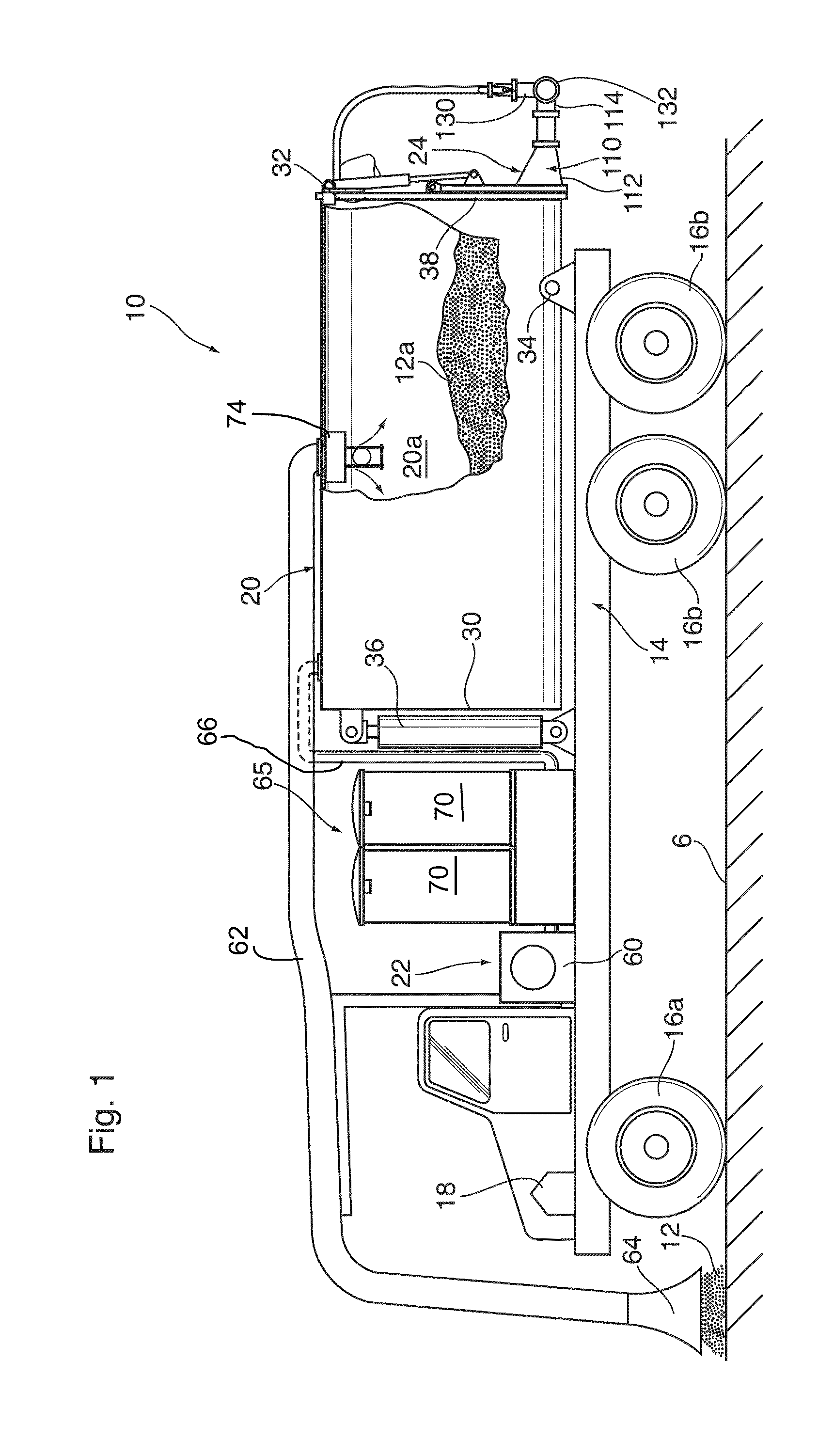
[0023]Reference is made to FIG. 1 which illustrates a vacuum truck 10 for use in the collection, transport, and subsequent discharge of particulate waste revert material 12 produced in underground mining operations in accordance with a preferred embodiment. As will be described, in operation the truck 10 is operable to collect particulate revert material 12 off of the ground 6 and store it for transport and subsequent discharge into a remote storage silo 8 (FIG. 7) located at a recycling or processing facility.

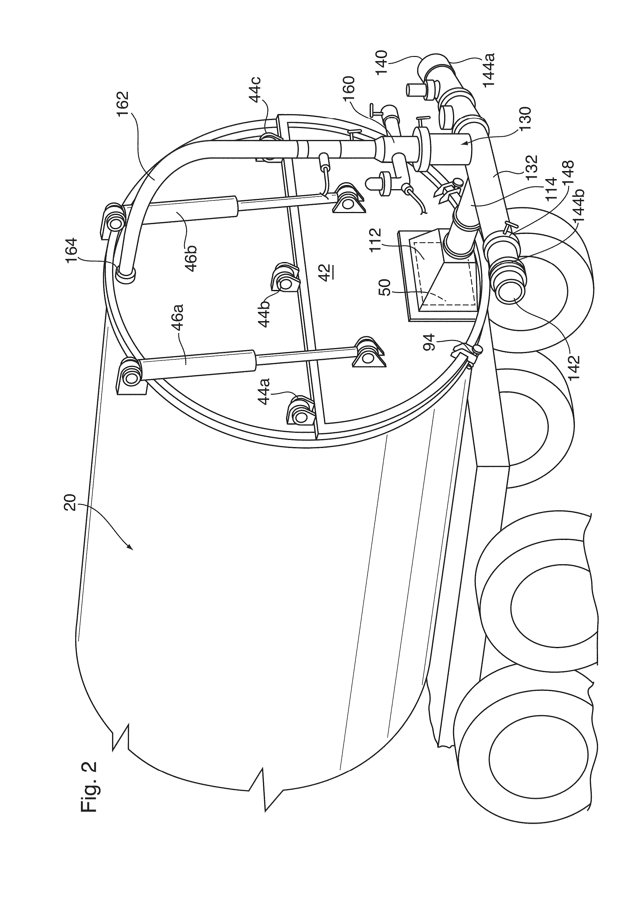
[0024]The truck 10 includes a truck frame 14 mounted on front and rear sets of ground wheels 16a,16b, and although not essential, is most preferably powered in both movement and vacuum operation by way of a diesel motor 18. The vacuum truck 10 is provided with material storage or collection tank 20, a pneumatic waste collection assembly 22 and a pneumatic waste discharge assembly 24 mounted on the frame 14.

[0025]FIG. 1 shows best the collection tank 20 as having a generally cy...


PUM


Abstract

A vacuum truck for the collection and discharge of a waste particulate material which includes a storage tank, waste collection and discharge assemblies and an air pump assembly. The air pump assembly is operable to induce negative and positive pressures within the storage tank. The collection assembly includes a vacuum inlet for fluid flow between the vacuum inlet and the storage tank inlet during air pump operation to induce said negative pressure. The waste discharge assembly includes a discharge conduit for conveying a pressurized fluid flow and entrained collected material from a tank materials outlet to an outlet end while the air pump assembly is operated to induces a positive pressure.

Description

SCOPE OF THE INVENTION[0001]The present invention relates to a collection and discharge assembly for use with a vacuum-type collector, and more particularly a vacuum truck pneumatic transfer system for the collection, transportation and subsequent discharge of a particulate material, and preferably spillage and / or waste material from steel making, mining and / or ore processing operations.BACKGROUND OF THE INVENTION[0002]Vacuum trucks for the collection and transport of solid waste materials are known. Such trucks are typically provided with a material collection or waste storage tank which is mounted on a truck frame or chassis. A vacuum source is provided to draw air into the storage tank from a suction or vacuum inlet placed in proximity to the material to be collected. Following collection, the truck is thereafter used to move the collected material to either a disposal or waste recycling site, where the collected material is discharged.[0003]To discharge the collected material fr...

Claims


Application Information

Patent Timeline
IPC IPC(8): B60P1/60B65G53/24
CPCB60P1/60E01H1/0836
Inventor BLAIS, DENISSMITH, SHAYNE
Owner BM METALS SERVICES
Learn More