Light-bar adhesion fixture and corresponding light-bar adhesion method

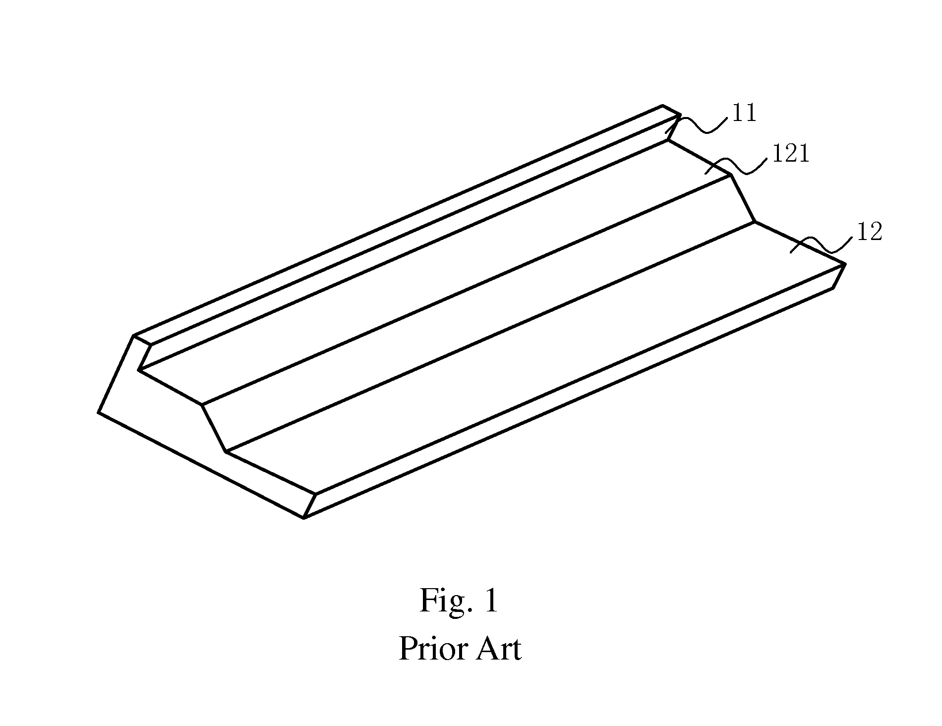
a technology of light-bars and adhesive fixtures, which is applied in the direction of paper/cardboard containers, lighting support devices, instruments, etc., can solve the problems of difficult to control the thickness, easy to be uneven in the thickness of the position limiting structure 121, and difficult to control the linearity of the light-bar

Inactive Publication Date: 2014-01-09
TCL CHINA STAR OPTOELECTRONICS TECH CO LTD
View PDF6 Cites 4 Cited by
  • Summary
  • Abstract
  • Description
  • Claims
  • Application Information

AI Technical Summary

Benefits of technology

[0006]One of the objects of the present invention is to provided with a light-bar adhesion fixture and a corresponding light-bar adhesion method, which can conveniently achieve a linear adhesion of a light emitting diode (LED), so as to solve the existing technological problems that the manufacture cost of the heat sink is higher, or the thickness of the position limiting portion of the light bar is difficult to be controlled causing a light leak.
[0023]In comparison with an existing light-bar adhesion method, the light-bar adhesion fixture and the corresponding light-bar adhesion method according to the present invention can conveniently achieve a linear adhesion of an LED, so as to solve the existing technological problems that the manufacture cost of the heat sink is higher, or the thickness of the position limiting portion of the light bar is difficult to be controlled causing a light leak.

Problems solved by technology

However, because the position limiting structure 121 of this type of heat sinks has a certain thickness, it is difficult to control the thickness of the position limiting structure 121 when it is made by means of sheet metal punching, so the thickness of the position limiting structure 121 is easy to be uneven.
As a result, it is difficult to control the linearity of the light bar when the LED light bar is adhered on the heat sink.
If using an extrusion molding method to manufacture the above-mentioned position limiting structure 121, it can well control the thickness of the position limiting structure 121, but it needs processing a secondary working, so the manufacture cost of the heat sink is increased.

Method used


Image

  • Light-bar adhesion fixture and corresponding light-bar adhesion method
  • Light-bar adhesion fixture and corresponding light-bar adhesion method
  • Light-bar adhesion fixture and corresponding light-bar adhesion method

Examples


Embodiment Construction

[0031]The description of the preferred embodiments refers to the drawings, so as to illustrate the specific embodiments of the present invention which can be carried out. Furthermore, the directional terms described in the present invention, such as upper, lower, front, rear, left, right, inner, outer, side and etc., are only directions referring to the accompanying drawings, so that the used directional terms are used to describe and understand the present invention, but the present invention is not limited thereto.

[0032]In the drawings, the units with the similar structure use the same numerals.

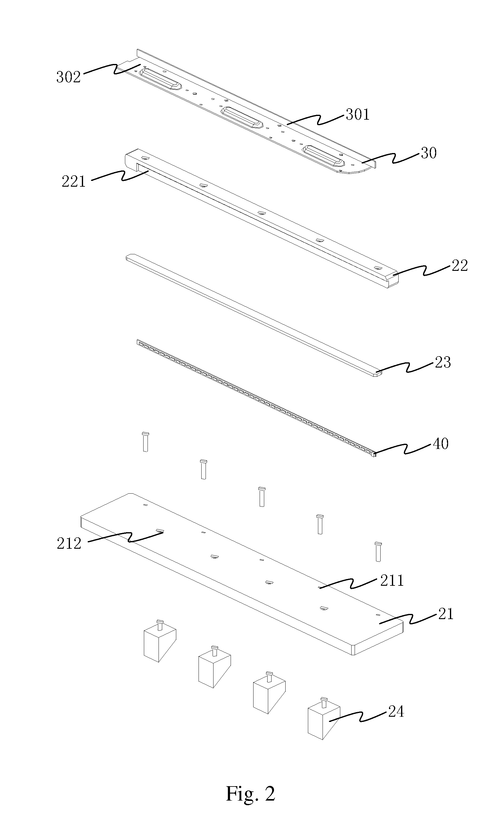
[0033]Referring now to FIGS. 2 to 5, an exploded structural schematic view of a light-bar adhesion fixture of a preferred embodiment according to the present invention is illustrated in FIG. 2; an operational schematic view of the light-bar adhesion fixture of the preferred embodiment according to the present invention is illustrated in FIG. 3; a cross-sectional schematic view of the light-...


PUM

PropertyMeasurementUnit
thicknessaaaaaaaaaa
widthaaaaaaaaaa
heightaaaaaaaaaa

Abstract

The present invention relates to a light-bar adhesion fixture and a corresponding light-bar adhesion method. The light-bar adhesion fixture comprises a base, a position limiting member disposed on a surface of the base and comprising a groove structure for fixing a corresponding heat sink; and a strip-like pad used to cooperate with the groove structure to fix a light emitting diode (LED) light bar on a light-bar fixing portion of the heat sink. The present invention further relates to a light-bar adhesion method. The light-bar adhesion fixture and the corresponding light-bar adhesion method according to the present invention can conveniently achieve a linear adhesion of the LED light bar.

Description

FIELD OF THE INVENTION[0001]The present invention relates to a field of light source manufacture, and more particularly to a light-bar adhesion fixture and a corresponding light-bar adhesion method.BACKGROUND OF THE INVENTION[0002]Existing light emitting diode (LED) backlight modules all use heat sinks to dissipate heat of LED light bars. FIG. 1 is a structural schematic view of a heat sink of an existing LED light bar, wherein the heat sink comprises a light-bar fixing portion 11 and a connecting portion 12, wherein a position limiting structure 121 is disposed on the connecting portion 12. The light-bar fixing portion 11 is used for fixing the LED light bar; and the position limiting structure 121 of the connecting portion 12 is used to limit the position of the fixed light bar, so as to prevent the LED light bar from generating up-down offset.[0003]However, because the position limiting structure 121 of this type of heat sinks has a certain thickness, it is difficult to control t...

Claims


Application Information

Patent Timeline
Patent Type & Authority Applications(United States)
IPC IPC(8): F21V21/00B32B37/12
CPCG02B6/0073G02B6/0085Y10T156/10
Inventor ZHANG, YANXUEHSIAO, YU-CHUN
Owner TCL CHINA STAR OPTOELECTRONICS TECH CO LTD
Why Eureka
Try Eureka