
Pressure sensitive transducer assembly and control method for a system including such an assembly

Active Publication Date: 2014-01-09
APTIV TECH LTD
View PDF3 Cites 17 Cited by
  • Summary
  • Abstract
  • Description
  • Claims
  • Application Information

AI Technical Summary

Benefits of technology

This patent describes a pressure sensitive transducer assembly that has a few modifications needed to connect it to an external control unit. The assembly includes a force sensing resistor that works under preload condition and can detect when the assembly is not working properly. An auxiliary trace is included to help detect preload lost. The assembly can also be used with a central control unit that applies a reference voltage or frequency to the assembly to confirm the preload condition is intact. This invention provides a cost-effective and efficient solution for applying pressure sensing technology in various industrial applications.

Problems solved by technology

Current transducer assemblies are not fully satisfactory because it is not possible to detect easily when the assembly is disconnected from the control circuit as it provides the same output voltage for different situations.
However, adding new pins for test purpose implies a higher cost for the connector and for the force sensing resistor.
Visual check and camera testing either EOLT or in-line also increase costs and assembly time and cannot easily implemented due to a small space and bad visibility of the connector area within the product.
Further, the only electronics failure that can be detected is a short to ground or to power supply.
Moreover, these common solutions do not permit to distinguish an electronics failure from a use of the force sensing resistor out of its normal operating range.
Resolution of an analog driver is not sufficient to detect loss of preload condition.

Method used


Image

  • Pressure sensitive transducer assembly and control method for a system including such an assembly
  • Pressure sensitive transducer assembly and control method for a system including such an assembly
  • Pressure sensitive transducer assembly and control method for a system including such an assembly

Examples


Embodiment Construction

[0032]In the following description, similar features could be designated by same reference.

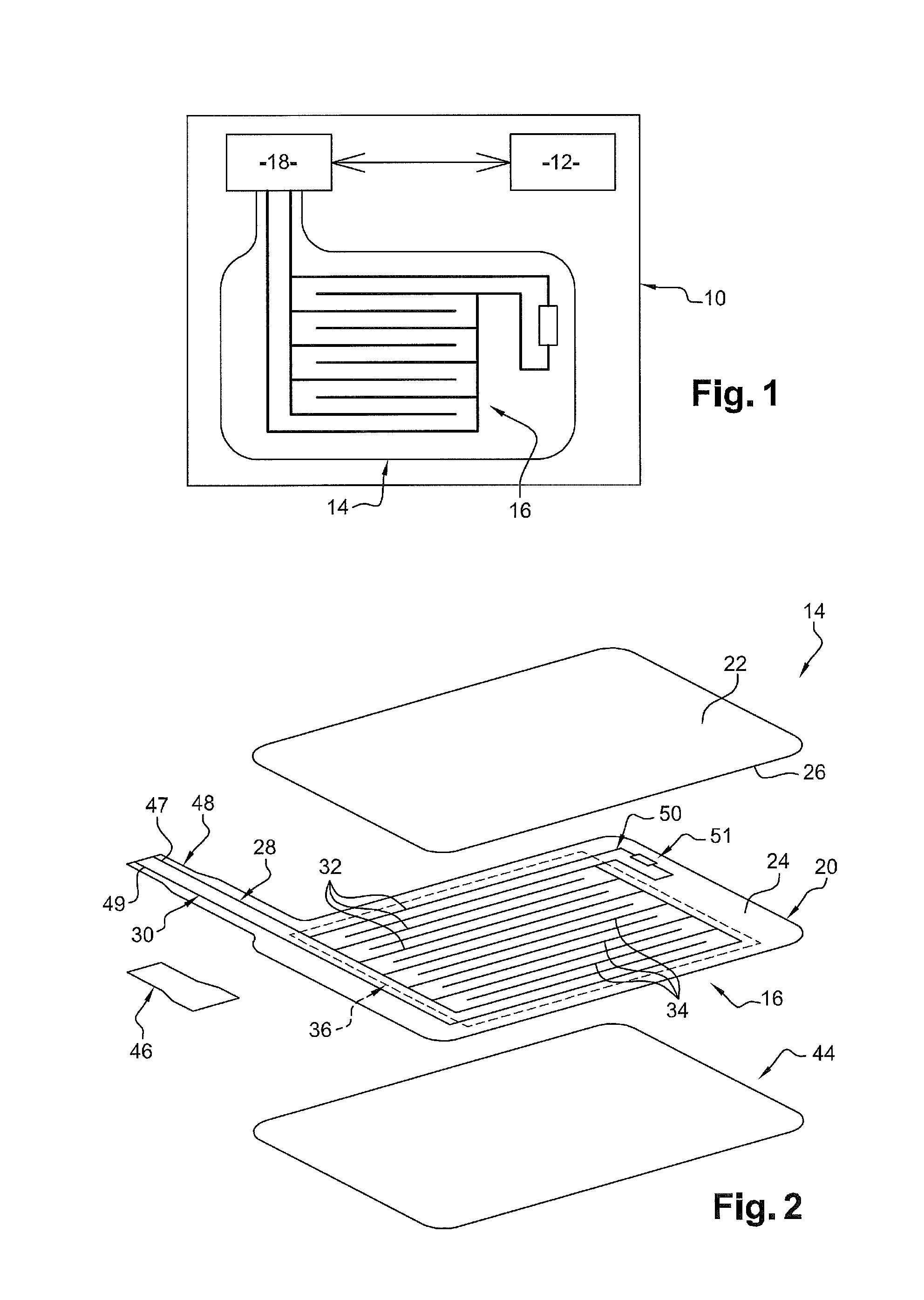
[0033]Referring now to FIG. 1, a system 10 comprising a central unit 12 which controls a pressure sensitive transducer assembly 14 including a preloaded force sensing resistor 16 in accordance with a preferred embodiment of the present invention is shown. For example, the system 10 is a control panel for use in the passenger compartment of a car.

[0034]Said central unit 12 is connected to said assembly 14 through connection means 18 in order to apply a reference voltage Vref or frequency Fref to the assembly 14.

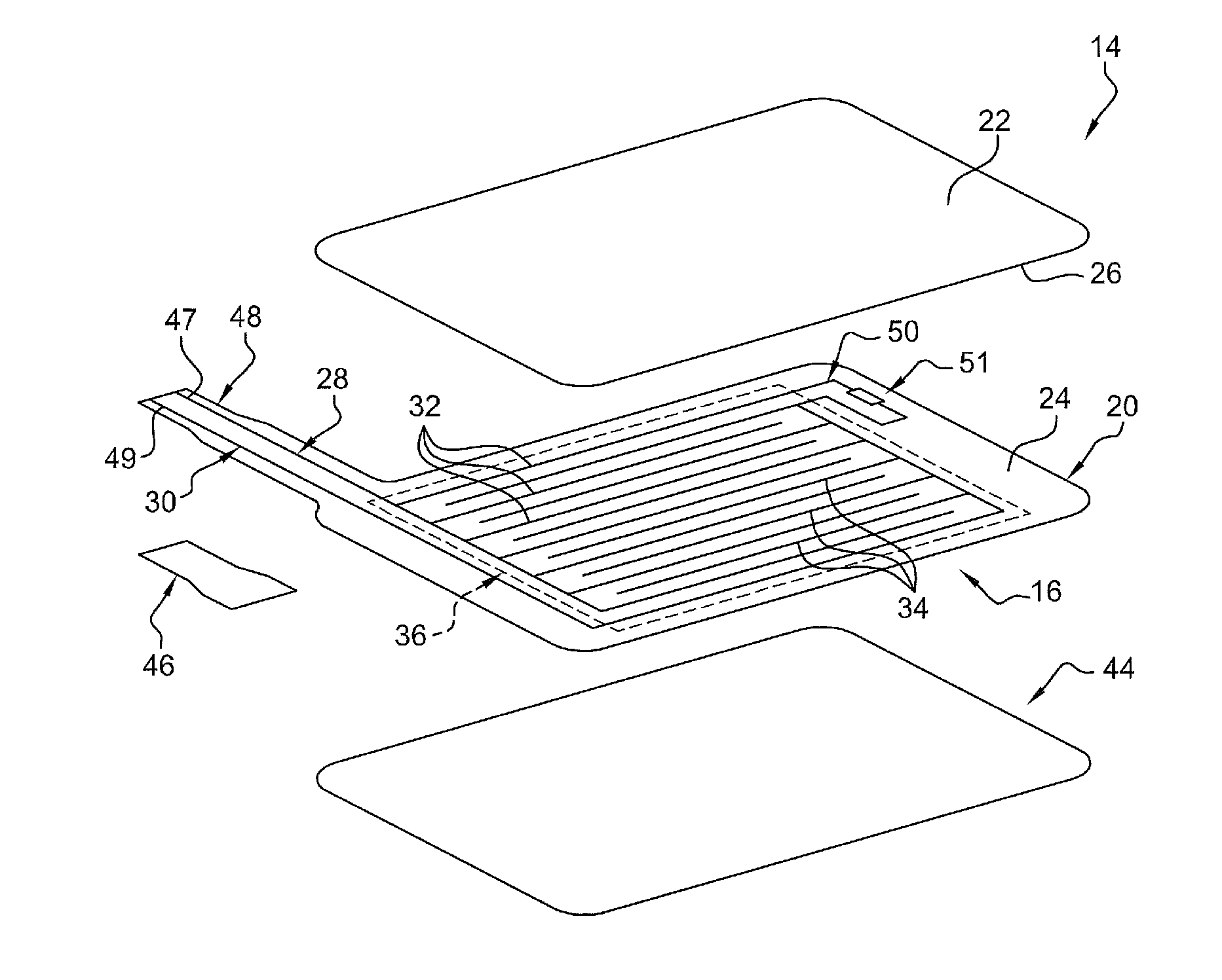
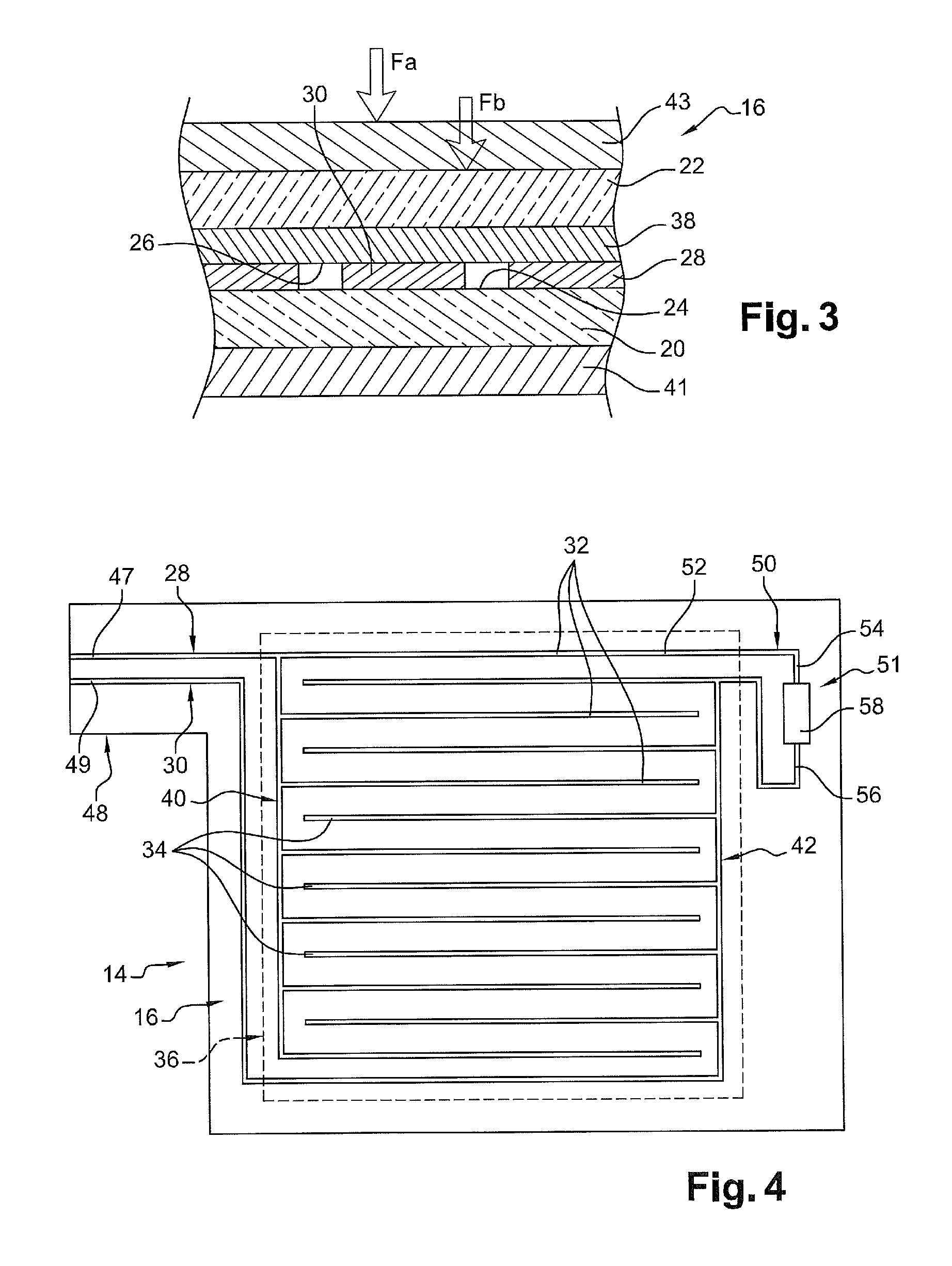
[0035]As shown in FIGS. 2, 3 and 4, assembly 14 comprises first 20 and second 22 substrates each having inner surfaces 24, 26. Preferably, said substrates 20, 22 are flexible in order to move towards the other one of the substrates in response to an applied force Fa. Substrates 20, 22 may be individual portions obtained from a sheet of material such as, for example, Mylar or PET (polyeth...


PUM


Abstract

Pressure sensitive transducer assembly that includes a force sensing resistor. The force sensing resistor includes: first and second substrates; at least a first and a second electrically conductive traces on the inner surface of the first substrate including interdigitated fingers defining a sensitive area; and a resistive layer facing the sensitive area. The force sensing resistor includes an auxiliary trace on the inner surface of the first substrate connecting the first trace to the second trace through a constant resistance that is not dependent on the force applied to the substrates. The constant resistance being of a value largely greater than the value of the variable resistance which can be measured indirectly between the fingers when an external force is applied to the substrates. A system and a control method are also proposed.

Description

CROSS-REFERENCE TO RELATED APPLICATION[0001]This application claims the benefit under 35 U.S.C. §371 of published PCT Patent Application Number PCT / EP 2011 / 063117, filed Jul. 4, 2011, claiming priority to European Patent Application Number EP10171502.7 filed on Jul. 30, 2010, and published as WO2012 / 013785 on Feb. 2, 2012, the entire contents of which is hereby incorporated by reference herein.TECHNICAL FIELD OF INVENTION[0002]The present invention relates to a pressure sensitive transducer assembly comprising a force sensing resistor.BACKGROUND OF INVENTION[0003]More particularly, the invention relates to such assembly, or tactile pressure sensor, used in a push button for detecting activation of the button.[0004]Generally, a pressure sensitive transducer assembly comprises a force sensing resistor with connection means, said force sensing resistor comprising: first and second substrates each having inner surfaces, wherein at least one of the substrates is flexible in order to move...

Claims


Application Information

Patent Timeline
IPC IPC(8): G01L1/22
CPCG01L1/2287G01L1/205G01L25/00
Inventor AUFRERE, ETIENNEMAHR, CHRISTOPHEAUBERGER, STEPHANEPRUD'HOMME, PIERRE-BENOIT
Owner APTIV TECH LTD
Learn More