
Systems and Methods For Carbon Dioxide Capture In Low Emission Turbine Systems

a low-emission turbine and carbon dioxide technology, applied in the direction of machines/engines, mechanical equipment, separation processes, etc., can solve the problems of increasing fuel demand, reducing power generation efficiency, and reducing power production, so as to reduce separation equipment size, reduce power generation efficiency, and enhance oil recovery

Inactive Publication Date: 2014-01-09
HUNTINGTON RICHARD A +6
View PDF8 Cites 78 Cited by
  • Summary
  • Abstract
  • Description
  • Claims
  • Application Information

AI Technical Summary

Benefits of technology

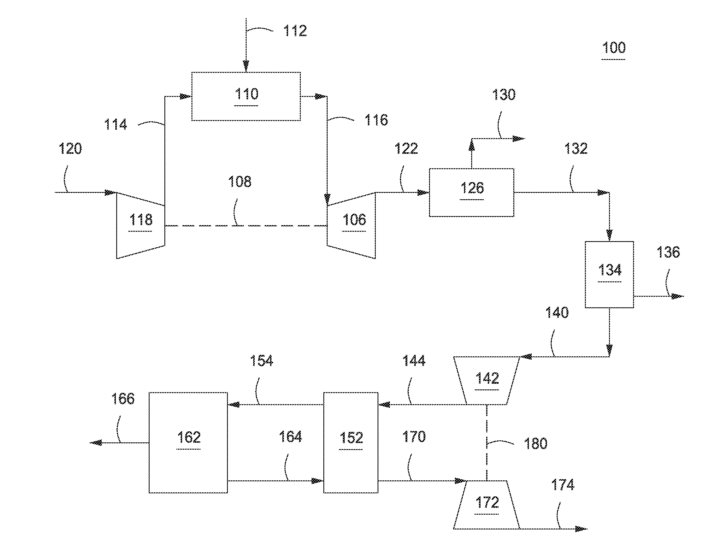
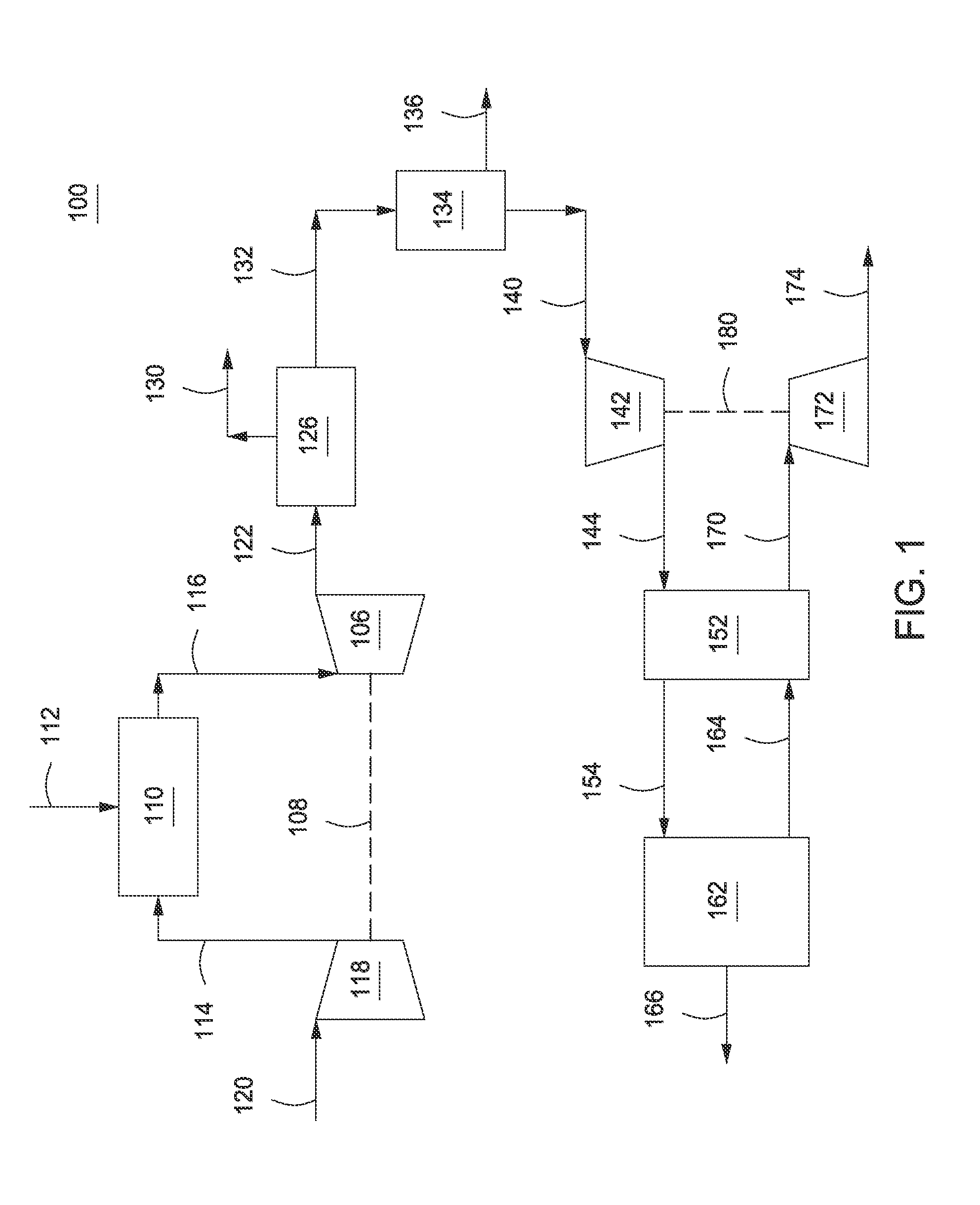
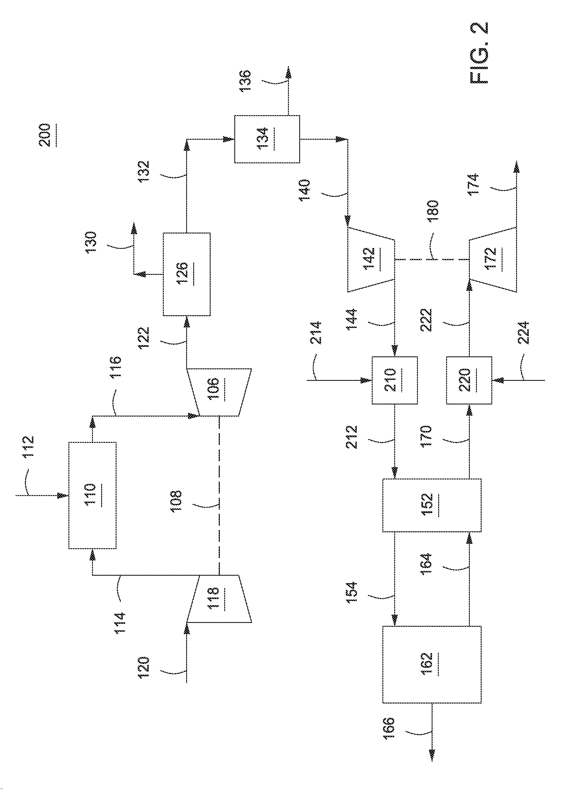
This patent describes a system that captures and utilizes the exhaust gases of low emission gas turbines in a natural gas combined cycle plant. Instead of releasing these gases into the atmosphere, the system uses an open Brayton cycle and a carbon dioxide separation process to generate power and a high-purity carbon dioxide stream. The carbon dioxide can be utilized in various ways, such as injecting it into hydrocarbon reservoirs for enhanced oil recovery or stored for future use. This system design reduces the size and complexity of the carbon dioxide separation equipment and improves its efficiency.

Problems solved by technology

However, both of these solutions are expensive and reduce power generation efficiency, resulting in lower power production, increased fuel demand and increased cost of electricity to meet domestic power demand.
In particular, the presence of oxygen, SOX, and NOX components makes the use of amine solvent absorption very problematic.
However, there are no commercially available gas turbines that can operate in such a cycle and the power required to produce high purity oxygen significantly reduces the overall efficiency of the process.
Capturing carbon dioxide from the exhaust of a gas turbine power plant is very expensive, however, for the following reasons: (a) the concentration of carbon dioxide in the exhaust stack is low, (b) a large volume of gas needs to be treated, (c) the pressure of the exhaust stream is low, (d) a large amount of oxygen is present in the exhaust stream, (e) additional cooling of the flue gas is required before entering a CO2 capture system, and (f) the flue gas is saturated with water after cooling, which increases the reboiler duty in a CO2 capture system.
All of these factors result in a high cost of carbon dioxide capture.

Method used


Image

  • Systems and Methods For Carbon Dioxide Capture In Low Emission Turbine Systems
  • Systems and Methods For Carbon Dioxide Capture In Low Emission Turbine Systems
  • Systems and Methods For Carbon Dioxide Capture In Low Emission Turbine Systems

Examples


Embodiment Construction

[0014]In the following detailed description section, the specific embodiments of the present disclosure are described in connection with preferred embodiments. However, to the extent that the following description is specific to a particular embodiment or a particular use of the present disclosure, this is intended to be for exemplary purposes only and simply provides a description of the exemplary embodiments. Accordingly, the disclosure is not limited to the specific embodiments described below, but rather, it includes all alternatives, modifications, and equivalents falling within the true spirit and scope of the appended claims.

[0015]Various terms as used herein are defined below. To the extent a term used in a claim is not defined below, it should be given the broadest definition persons in the pertinent art have given that term as reflected in at least one printed publication or issued patent.

[0016]As used herein, the term “natural gas” refers to a multi-component gas obtained...


PUM

PropertyMeasurementUnit
Pressureaaaaaaaaaa
Poweraaaaaaaaaa
Heataaaaaaaaaa

Abstract

Systems, methods, and apparatus are provided for generating power in low emission turbine systems and capturing and recovering carbon dioxide from the exhaust. In one or more embodiments, the exhaust is cooled, compressed, and separated to yield a carbon dioxide-containing effluent stream and a nitrogen-containing product stream.

Description

CROSS REFERENCE TO RELATED APPLICATIONS[0001]This application claims priority to U.S. Provisional Application 61 / 542,037 filed Sep. 30, 2011 entitled, SYSTEMS AND METHODS FOR CARBON DIOXIDE CAPTURE IN LOW EMISSION TURBINE SYSTEMS; U.S. Provisional Application 61 / 466,384 filed Mar. 22, 2011 entitled, LOW EMISSION TURBINE SYSTEMS HAVING A MAIN AIR COMPRESSOR OXIDANT CONTROL APPARATUS AND METHODS RELATED THERETO; U.S. Provisional Application 61 / 542,030 filed Sep. 30, 2011 entitled, LOW EMISSION TURBINE SYSTEMS INCORPORATING INLET COMPRESSOR OXIDANT CONTROL APPARATUS AND METHODS RELATED THERETO; U.S. Provisional Application 61 / 466,385 filed Mar. 22, 2011 entitled, METHODS FOR CONTROLLING STOICHIOMETRIC COMBUSTION ON A FIXED GEOMETRY GAS TURBINE SYSTEM AND APPARATUS AND SYSTEMS RELATED THERETO; U.S. Provisional Application 61 / 542,031 filed Sep. 30, 2011 entitled, SYSTEMS AND METHODS FOR CONTROLLING STOICHIOMETRIC COMBUSTION IN LOW EMISSION TURBINE SYSTEMS; U.S. Provisional Application 61...

Claims


Application Information

Patent Timeline
IPC IPC(8): F02C3/00C01B32/50
CPCF02C3/00B01D53/62B01D2251/306B01D2251/606B01D2257/504F02C3/04F02C6/18F05D2260/61F05D2260/611Y02E20/16Y02C20/40
Inventor HUNTINGTON, RICHARD A.MITTRICKER, FRANKLIN F.SITES, OMER ANGUSDHANUKA, SULABH K.O'DEA, DENNIS M.OELFKE, RUSSELL H.DENTON, ROBERT D.
Owner HUNTINGTON RICHARD A
Learn More