Footwear sanitizing and deodorizing system exposing light-activated photocatalytic oxidation coating

a technology of photocatalytic oxidation and shoe sanitizing, which is applied in the direction of material analysis using wave/particle radiation, instruments, and therapy, can solve problems such as light leakage, and achieve the effects of removing dampness found inside the shoe, less expensive, and convenient acquisition

Active Publication Date: 2014-01-02
PEDIFIX
View PDF8 Cites 31 Cited by
  • Summary
  • Abstract
  • Description
  • Claims
  • Application Information

AI Technical Summary

Benefits of technology

The present patent relates to methods and apparatus for introducing light and forced air flow into footwear to alter the environment inside it and to deodorize it. The technical effects include the ability to destroy microorganisms, prevent their growth, and deodorize the footwear. Additionally, the patent describes methods for preventing unfavourable exposure to UV light and methods for using containers to reduce the intensity of ambient light inside the footwear. The patent also mentions a filtration system to reduce odor in the footwear circulated with forced air.

Problems solved by technology

A light leak could be the result of improper insertion of the UV light source into the shoe.

Method used


Image

  • Footwear sanitizing and deodorizing system exposing light-activated photocatalytic oxidation coating
  • Footwear sanitizing and deodorizing system exposing light-activated photocatalytic oxidation coating
  • Footwear sanitizing and deodorizing system exposing light-activated photocatalytic oxidation coating

Examples


first embodiment

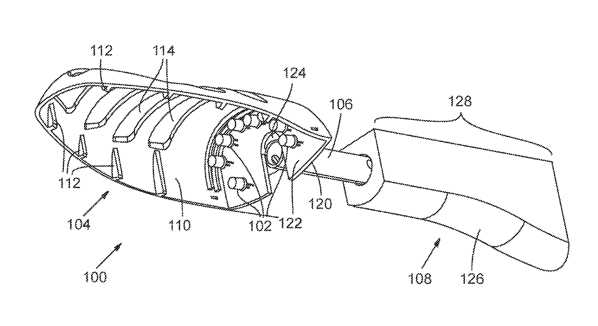
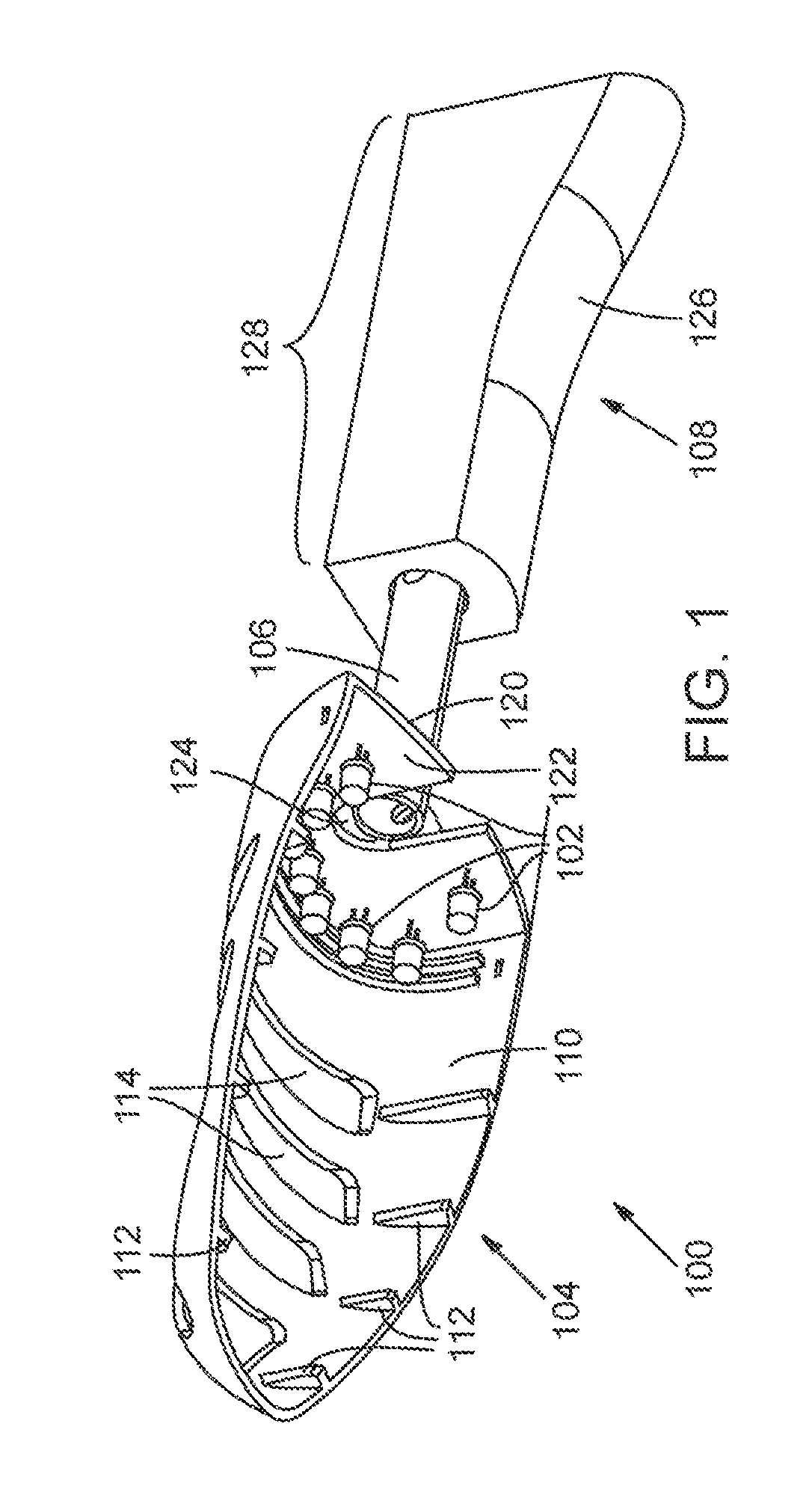
[0034]FIG. 1 shows, as a first embodiment, a shoe tree 100 configured to accommodate a semi-circular linear array of LEDs 102 that, in a preferred embodiment, radiate germicidal UV light, or white light including a UV component, into the toe of a shoe in which shoe tree 100 is inserted. A UV LED that emits light within the germicidal range and is suitable for use in LED array 102 is a Model No. UVTOP255-BL-T039, available from Roithner LaserTechnik, Vienna, Austria. Visible light (blue or white) LEDs, which are readily available, can be used to inhibit or prevent further growth of microorganisms in the shoe. Shoe tree 100 includes a hollow forepart 104 connected by an extensible one-piece cylindrical spine 106 to a heel section 108.

[0035]Forepart 104 is a curved half-shell structure having an inner surface 110 that supports multiple inwardly directed, spaced-apart structural tabs 112 and having multiple generally rectangular, elongated slots 114 that are spaced apart in a transverse...

second embodiment

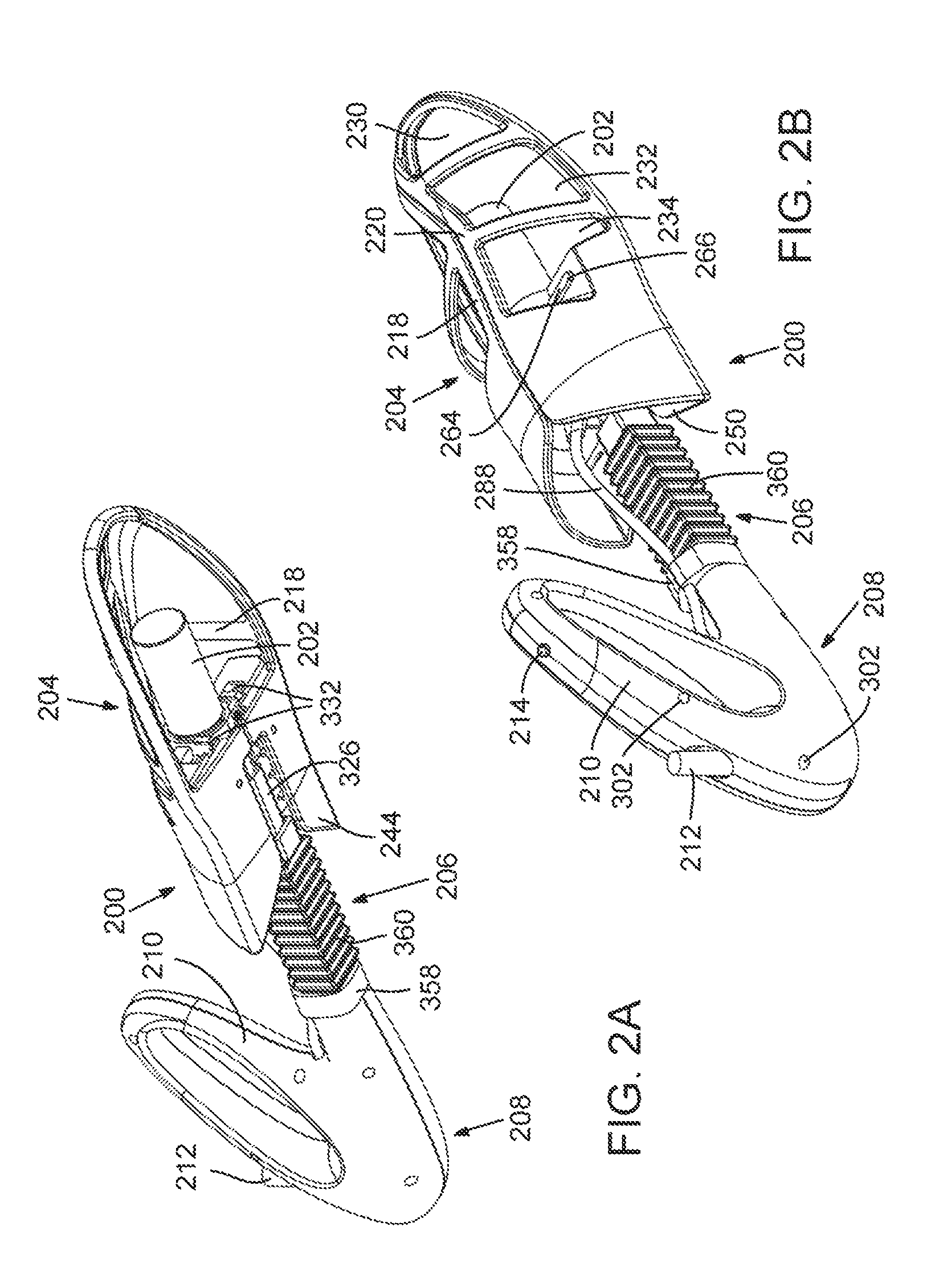
[0036]FIGS. 2A, 2B, 3A-3G, and 4-7 show, as a second embodiment, a sanitizing shoe tree 200 in which a UV germicidal bulb 202 is installed, instead of LED array 102 used in shoe tree 100. Shoe tree 200 includes a hollow forepart 204 connected by a spring-loaded extensible spine 206 to a heel section 208. Electronic components enabling UV safety features are concealed throughout heel section 208, spine 206, and hollow forepart 204 and are, therefore, not apparent from the exterior of shoe tree 200. Heel section 208 terminates in a closed loop-shaped handle 210 to facilitate length adjustment; spring-loaded extensible spine 206 allows linear motion into and out of heel section 208; and hollow forepart 204 features large openings, or windows, of non-uniform size and shape through which light can propagate into the interior of a shoe. A power supply cord 212 extends from the rear of heel section 208 and provides electrical power for delivery to UV germicidal bulb 202 as described below....


PUM

PropertyMeasurementUnit
wavelengthsaaaaaaaaaa
wavelength rangeaaaaaaaaaa

Abstract

Introducing ultraviolet (UV) light to activate a photocatalytic oxidation coating applied to interior portions of footwear alters the environment inside a shoe or other footwear to destroy microorganisms or inhibit their growth. Visible light can also be used to prevent further microorganism growth. Introducing forced air flow through the footwear removes dampness in and thereby deodorizes the footwear. A preferred embodiment comprises an adjustable shoe tree equipped with a UV germicidal light source and electronic safeguards that prevent appreciable leakage of UV radiation outside the shoe.

Description

RELATED APPLICATIONS[0001]This application is a continuation-in-part of U.S. patent application Ser. No. 13 / 160,066, filed Jun. 14, 2011, and now U.S. Pat. No. 8,466,433; which is a continuation-in-part of U.S. patent application Ser. No. 12 / 281,910, filed Sep. 5, 2008, and now U.S. Pat. No. 7,960,706; which is a 371 of International Application No. PCT / US07 / 63925, filed Mar. 13, 2007; which claims benefit of U.S. Provisional Patent Application Nos. 60 / 781,276 and 60 / 881,552, filed Mar. 13, 2006 and Jan. 22, 2007, respectively.COPYRIGHT NOTICE[0002]© 2013 Shoe Care Innovations, Inc. A portion of the disclosure of this patent document contains material that is subject to copyright protection. The copyright owner has no objection to the facsimile reproduction by anyone of the patent document or the patent disclosure, as it appears in the Patent and Trademark Office patent file or records, but otherwise reserves all copyright rights whatsoever. 37 CFR §1.71(d).TECHNICAL FIELD [0003]The...

Claims


Application Information

Patent Timeline
Patent Type & Authority Applications(United States)
IPC IPC(8): A61L2/08
CPCA61L2/088A61L2/10A61L2/084A61L2/24A61L9/205A61L2209/11A61L2209/12
Inventor ULLMAN, ADAM
Owner PEDIFIX
Why Eureka
Try Eureka