
Methods and systems for removing diamond-diamond bonding catalysts from polycrystalline diamond

a diamond bonding catalyst and diamond technology, applied in the field of methods and systems for removing diamond-diamond bonding catalysts from polycrystalline diamond, can solve the problems of limited depth to which cobalt can be removed from a pdc by state-of-the-art leaching process, and the potential for damage to pdc during use, so as to facilitate the formation of diamond-diamond bonds

Active Publication Date: 2013-12-26
EVE BIT SALES
View PDF1 Cites 16 Cited by
  • Summary
  • Abstract
  • Description
  • Claims
  • Application Information

AI Technical Summary

Benefits of technology

The patent text describes methods and systems for removing cobalt from polycrystalline diamond or structures formed from polycrystalline diamond, such as PDCs. The methods involve applying a leaching agent to the diamond and heating it to a suitable temperature to facilitate the removal of cobalt from the diamond. The leaching agent may be in the form of a liquid or slurry and may include oxidizing agents or other substances to facilitate the removal of cobalt. The process of leaching cobalt from the diamond may involve exposing it to a pressure above atmospheric pressure. The patent also describes the use of a hot hole simulator for applying the leaching agent to the diamond surfaces. The system may include a sensor to monitor the amount of cobalt removed from the diamond. Overall, the patent provides methods and systems for effectively removing cobalt from polycrystalline diamond structures.

Problems solved by technology

The depths to which cobalt can be removed from a PDC by state-of-the-art leaching processes is limited, however, because the chemicals that are currently used in leaching processes will dissolve, degrade or otherwise attack the substrates (e.g., a cemented carbide, such as tungsten carbide, etc.) that carry the PDCs of the cutting elements.
Thus, cobalt, and its potential for damaging the PDC during use, remain within the interior of the PDC.

Method used


Image

  • Methods and systems for removing diamond-diamond bonding catalysts from polycrystalline diamond
  • Methods and systems for removing diamond-diamond bonding catalysts from polycrystalline diamond

Examples


Embodiment Construction

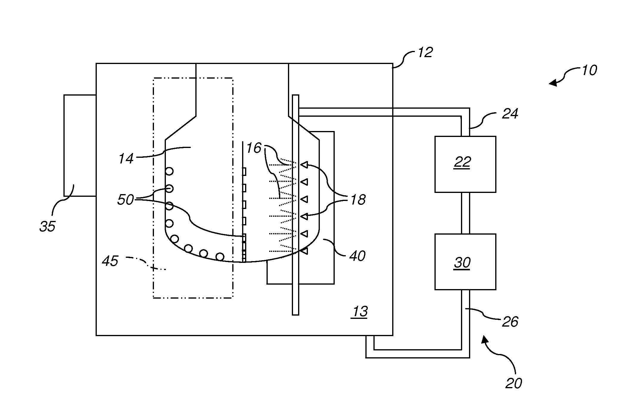
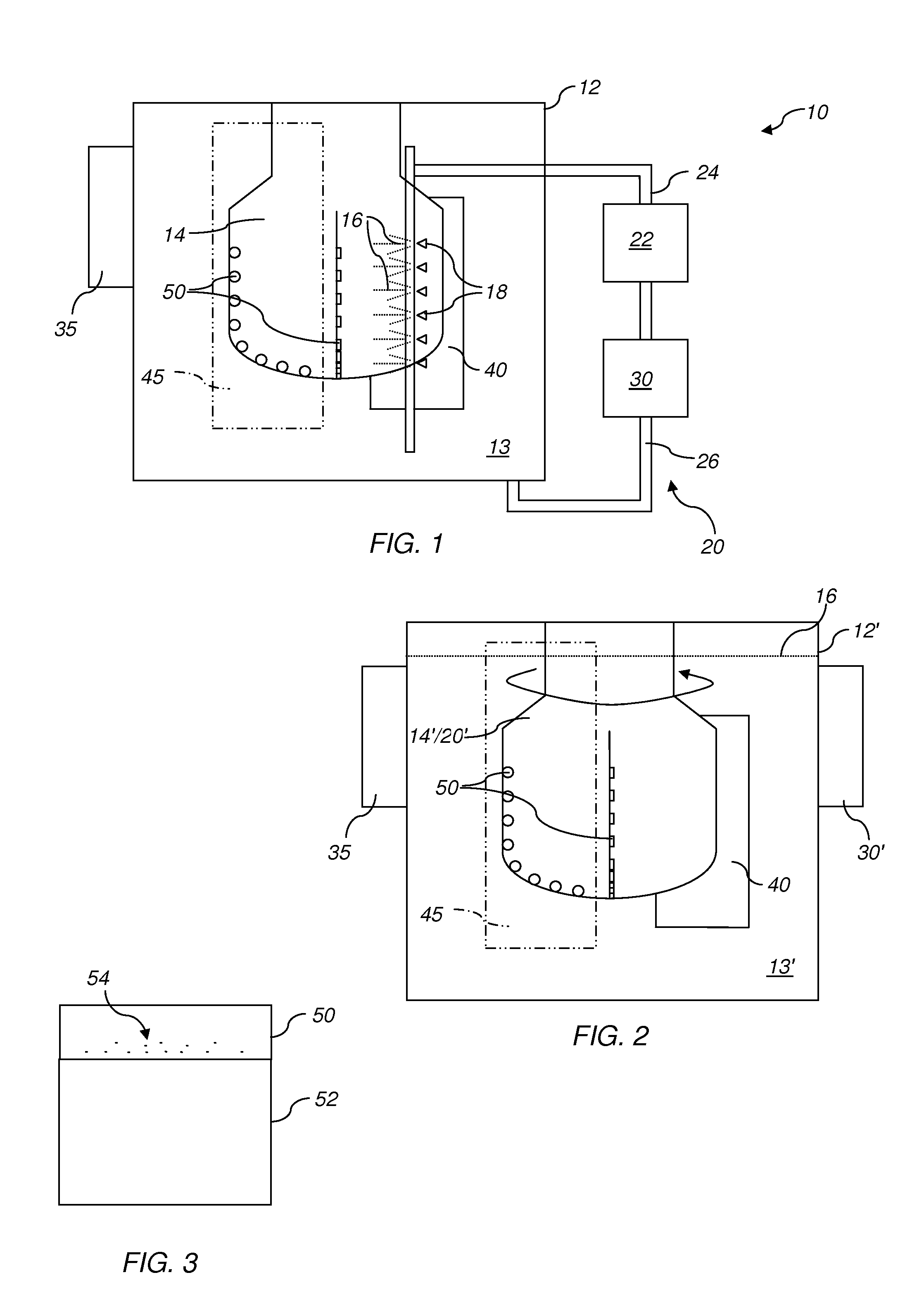
[0020]FIGS. 1 and 2 illustrate embodiments of leaching systems 10 and 10′, respectively, for removing cobalt from one or more PDCs. A leaching system 10, 10′, etc., that incorporates teachings of this disclosure may comprise a hot hole simulator. Each leaching system 10, 10′ includes a container 12, 12′ that is configured to artificially simulate a hot hole drilling environment. Each container 12, 12′ includes an interior 13, 13′ configured to receive and hold one or more PDCs 50 (or other structures that include polycrystalline diamond) in a manner that facilitates or enables exposure of each PDC 50 to a leaching agent and / or to leaching conditions.

[0021]As shown by FIG. 2, a container 12′ may include a support 14′ within its interior 13′. The support 14′ may be configured to hold one or more PDCs 50 in place during the leaching process. In a specific embodiment, the support 14′ may comprise or be configured to at least functionally resemble a bit body (e.g., a bit body of a rotary...


PUM

PropertyMeasurementUnit
temperatureaaaaaaaaaa

Abstract

Methods for removing, or leaching, cobalt or other diamond-diamond bonding catalysts from polycrystalline diamond compacts (PDCs) or other structures formed from polycrystalline diamond include leaching under conditions that simulate use of PDCs in a hot hole drilling environment. A leaching agent may be formulated, when used under appropriate conditions, to remove or substantially remove cobalt or another catalyst from polycrystalline diamond without dissolving, degrading or otherwise attacking a substrate that supports or carries the polycrystalline diamond. The leaching agent may include one or more components that mimick the chemicals or conditions to which a PDC would be exposed in a hot hole drilling environment. Polycrystalline diamond structures from which cobalt or another diamond-diamond bonding catalyst has been removed or substantially removed are also disclosed, as are systems for leaching cobalt or other diamond-diamond bonding catalysts from polycrystalline diamond.

Description

TECHNICAL FIELD[0001]This disclosure relates generally to methods and systems for removing, or leaching, cobalt or other diamond-diamond bonding catalysts from polycrystalline diamond compacts (PDCs) or other structures formed from polycrystalline diamond and, more specifically, to methods and systems in which conditions present in a so-called “hot hole” drilling environment, or a high-pressure, high-temperature (HPHT) environment, may be simulated to leach cobalt or other diamond-diamond bonding catalysts from PDCs and other polycrystalline diamond structures. Leaching agents are also disclosed. This disclosure also relates to PDCs and other polycrystalline diamond structures from which cobalt or another diamond-diamond bonding catalyst has been removed or substantially removed.RELATED ART[0002]Polycrystalline diamond is typically formed using a process known as “sintering” under extremely high temperatures and pressures. A catalyst, often cobalt, is typically used to facilitate th...

Claims


Application Information

Patent Timeline
Patent Type & Authority Applications(United States)
IPC IPC(8): B01J3/06E21B10/567
CPCB01J19/24B01J19/28E21B10/567B01J3/06B01J4/002
Inventor EVE, JONATHAN
Owner EVE BIT SALES
Learn More