
Image forming apparatus

a technology of forming apparatus and forming tube, which is applied in the direction of electrographic process apparatus, instruments, optics, etc., can solve the problems of cost increas

Inactive Publication Date: 2013-12-19
CANON KK
View PDF8 Cites 2 Cited by
  • Summary
  • Abstract
  • Description
  • Claims
  • Application Information

AI Technical Summary

Benefits of technology

The present invention aims to provide an image forming apparatus that can transfer toner images onto paper without causing the paper to stick to the apparatus. Additionally, the apparatus does not require two power sources for the transfer process.

Problems solved by technology

That is, two transfer power sources are necessary, being therefore likely to lead to cost increase.

Method used


Image

  • Image forming apparatus
  • Image forming apparatus
  • Image forming apparatus

Examples


embodiment 1

Overall Structure of Image Forming Apparatus, and Operation of Apparatus

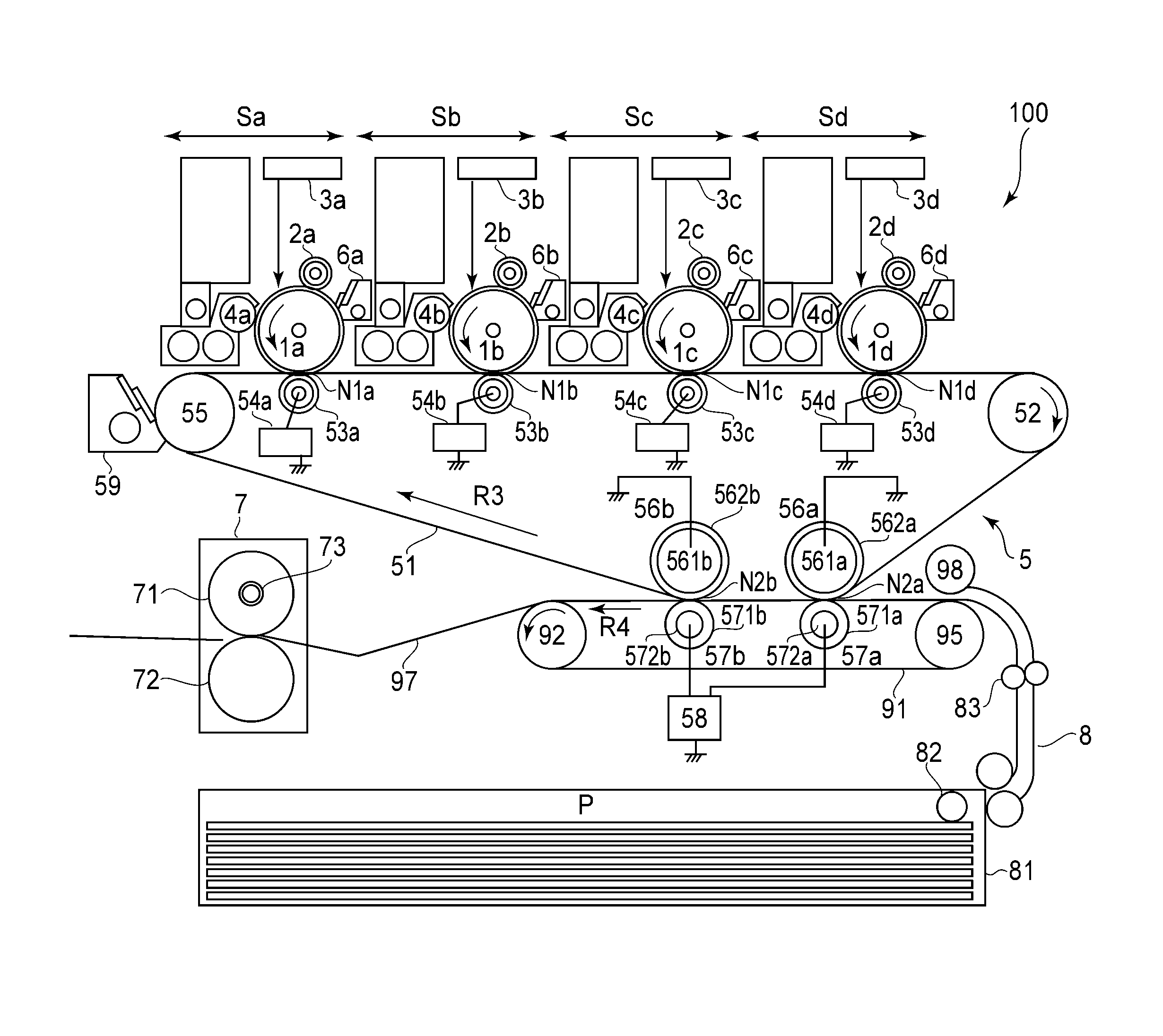
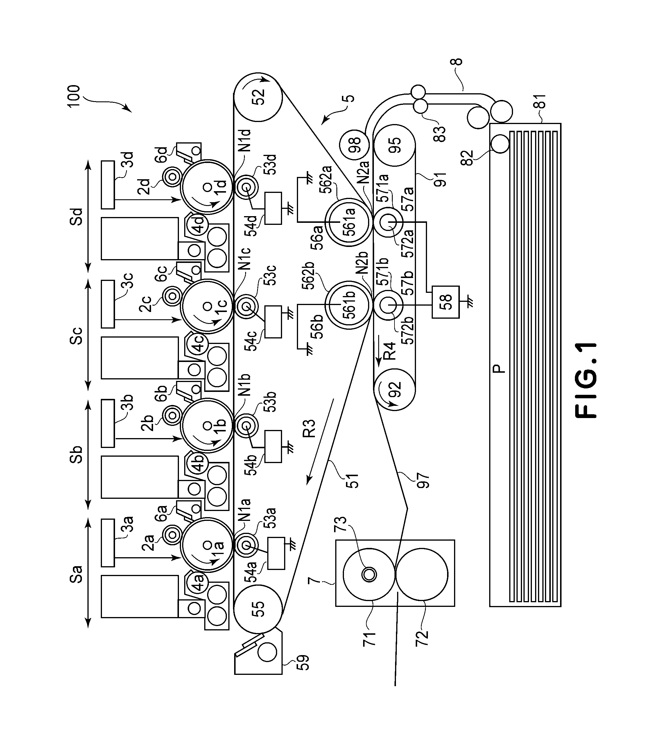
[0014]First, the overall structure of the image forming apparatus in this embodiment, and the operation of the apparatus, are described. FIG. 1 is a schematic sectional view of the image forming apparatus 100 in this embodiment. It shows the general structure of the apparatus.

[0015]Designated by referential codes Sa, Sb, Sc and Sd are processing units, as image formation stations, which form a toner image. The image formation stations Sa, Sb, Sc and Sd form yellow, magenta, cyan and black monochromatic images, respectively. The image formation stations Sa, Sb, Sc and Sd are the same in structure, although they are different in the color of the toner they use. Here, therefore, only the image formation station Sa is described.

[0016]The image formation station Sa comprises: a photosensitive drum 1a as an image bearing member; a charge roller 2a as the charging means for charging the peripheral surface of the photos...

embodiment 2

[0054]Next, the second embodiment of the present invention is described. The substantial portions of the second embodiment are the same as the counterparts of the first embodiment. Therefore, these portions are not going to be described here.

[0055]In this embodiment, the secondary transfer voltage power source 58 is in connection to the inside secondary transfer rollers 56a and 56b, and the outside secondary transfer rollers 57a and 57b are grounded. The secondary transfer voltage to be applied to the inside secondary transfer roller 56a and 56b to transfer a toner image is the same in polarity as toner.

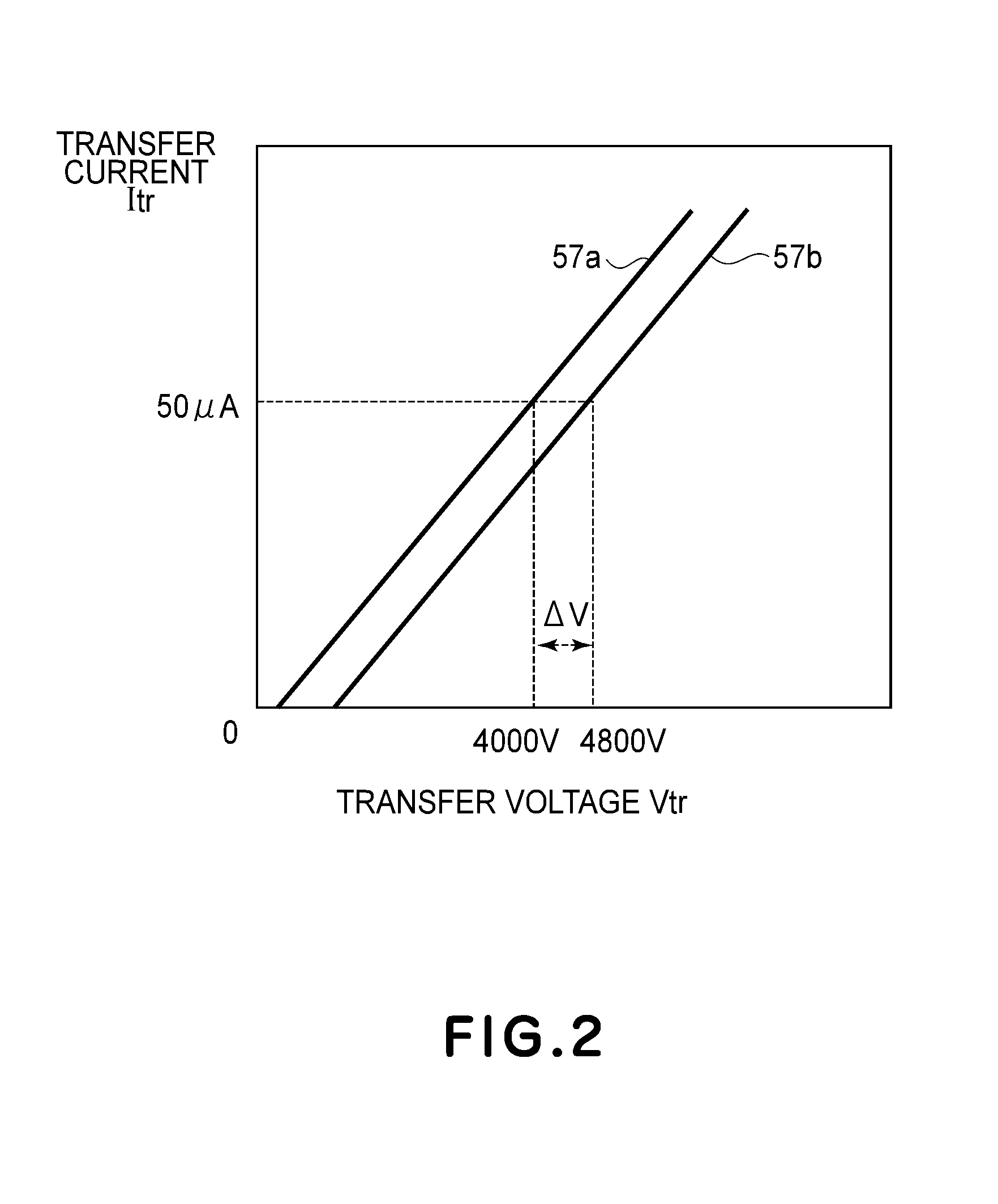
[0056]The image forming apparatus in this embodiment is structured so that the upstream inside secondary transfer roller 56a, which is in connection to the secondary transfer voltage power source 58, becomes the first electrical resistance, and the downstream inside secondary transfer roller 56b, which is in connection to the secondary transfer voltage power source 58, becomes the se...


PUM


Abstract

An image forming apparatus comprising an image carrying member for carrying a toner image; a intermediary member for carrying the toner image transferred from said image carrying member; a first transfer member for transferring the toner image from said intermediary member onto a sheet, said first transfer member having first resistance and being contacted to said intermediary member; a second transfer member for transferring the toner image from said intermediary member onto the sheet, said second transfer member having second resistance higher than the first resistance and being contacted to said intermediary member at a position downstream of said first transfer member; and voltage applying means, connected to both of said first transfer member and said second transfer member, for applying the same voltage to said first transfer member and to said second transfer member to transfer the toner image onto the sheet.

Description

TECHNICAL FIELD[0001]The present invention relates to an image forming apparatus, such as a copying machine, a printer, etc., which uses an electrophotographic image forming method or an electrostatic recording method.BACKGROUND ART[0002]It is desired that an image forming apparatus is capable of dealing with various recording mediums. Thus, some image forming apparatuses are provided with a primary transfer station, an intermediary transfer member, and a secondary transfer station. In operation, they form a toner image on their image bearing member such as a photosensitive drum, and transfer the toner image onto the intermediary transfer member in the primary transfer station. Then, they transfer the toner image onto a sheet of recording medium from the intermediary transfer member.[0003]Japanese Laid-open Patent Application 2004-29054 discloses an image forming apparatus having an upstream transfer roller and a downstream transfer roller which are provided to reduce the apparatus ...

Claims


Application Information

Patent Timeline
Patent Type & Authority Applications(United States)
IPC IPC(8): G03G15/01
CPCG03G15/1665G03G15/0189G03G15/1675G03G2215/0129G03G2215/1614
Inventor MOCHIZUKI, JUNSHIRAFUJI, YASUHITOTAKEUCHI, YASUSHIAKASHI, KAZUKIYO
Owner CANON KK
Learn More