Speaker
a speaker and speaker technology, applied in the field of speakers, can solve the problems of direct affecting the failure rate of the speaker in the drop test, and speaker failur
- Summary
- Abstract
- Description
- Claims
- Application Information
AI Technical Summary
Benefits of technology
Problems solved by technology
Method used
Image
Examples
embodiment 1
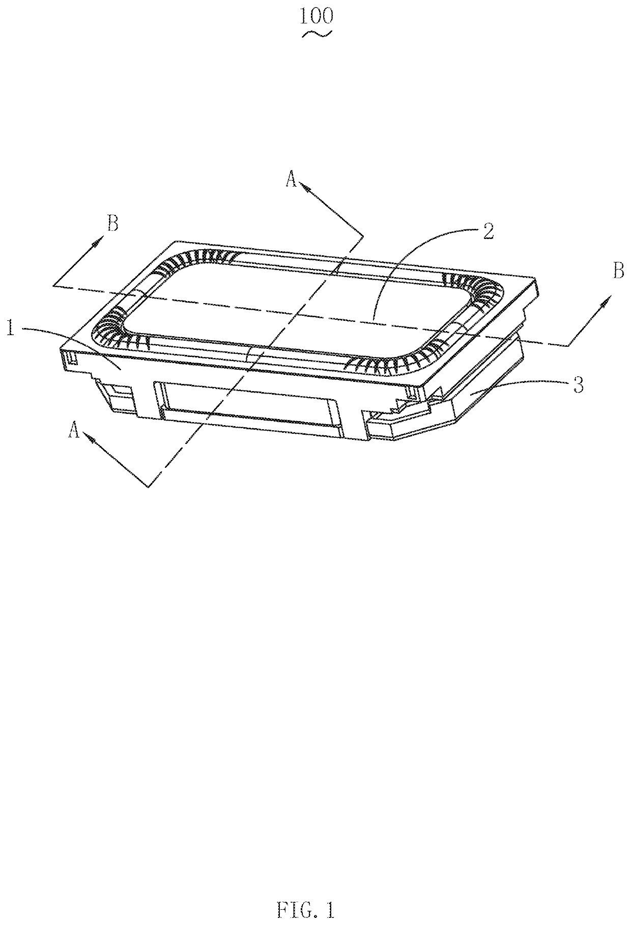
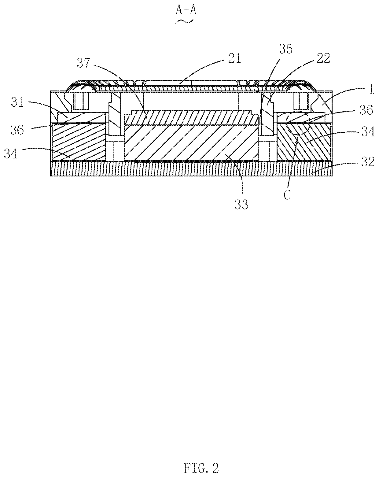
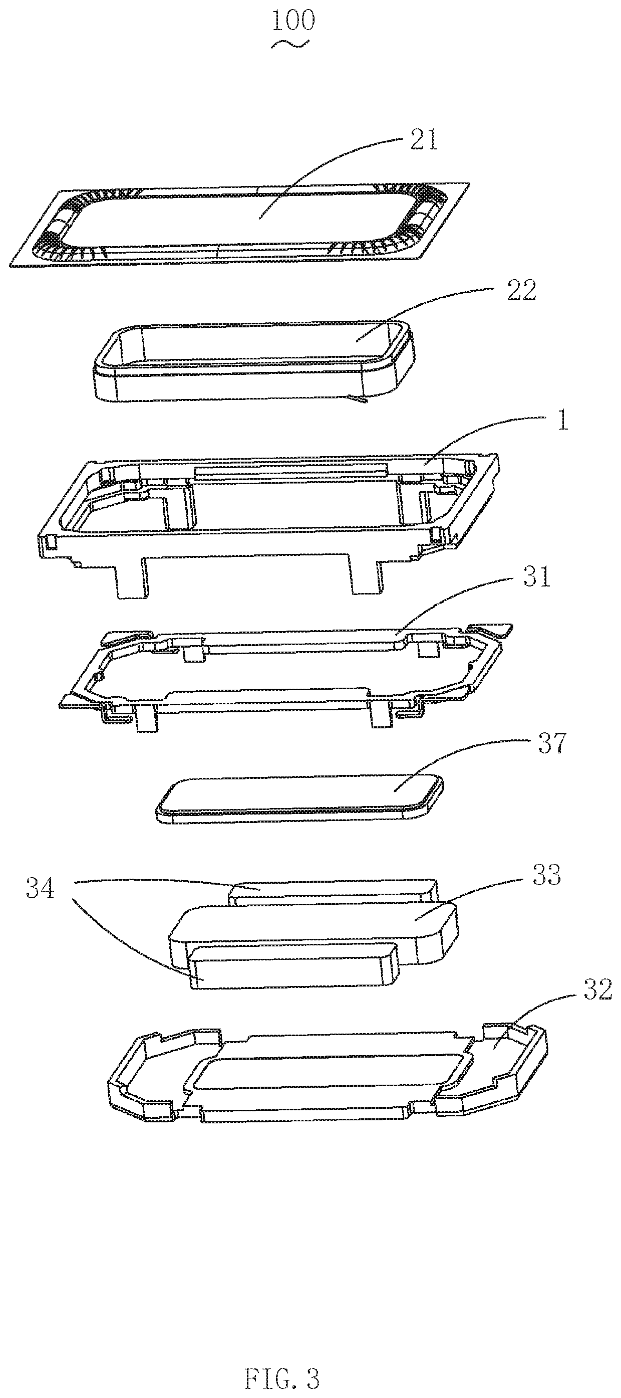
[0017]Please also refer to FIG. 1-3, wherein FIG. 1 is a three-dimensional diagram of structure of the speaker in accordance with an exemplary embodiment of the present disclosure; FIG. 2 is a cross-sectional diagram along the A-A line showing in FIG. 1; and FIG. 3 is a three-dimensional perspective diagram of the structure of the speaker exploded view showing in FIG. 1. The present disclosure provides a speaker 100, which comprises a frame 1, a vibration system 2 and a magnetic circuit system 3.
[0018]The vibration system 2 comprises a diaphragm 21 and voice coil assembly 22 driving the diaphragm 2 to vibrate for generating sound. The diaphragm 21 is located above the frame 1. The voice coil assembly 22 is connected to the diaphragm 21 and housed inside the frame 1. The magnetic circuit system 3 comprises a first clamping plate 31 housed in the frame 1, a yoke 32, a main magnetic 33 and a sub magnetic 34 disposed in the yoke 32. The sub magnetic 34 is located on both sides of the ma...
embodiment 2
[0020]As shown in FIG. 4, FIG. 4 is a plan view of the first clamping plate showing in the FIG. 1. The other features of the speaker provided in the embodiment 2 are the same as those in the embodiment 1, the difference is that the first clamping plate 31 further includes a splint frame 313, which is fixed to the frame 1.
[0021]It should be noted that the shape of the splint frame 313 is preferably the same as that of the yoke 32 edges around the circumference, but the shape of the splint frame 313 is any shape that can support the bonding portion 311 on the frame 1. The bonding portion 311 extends from the splint frame 313 in the direction toward the main magnetic 33. In the plane where the yoke 32 is located, the projection of the bonding portion 311 is completely coincides with the projection of the sub magnetic 34.
[0022]It should be pointed out that, on the basis of meeting the demand of miniaturization of the speaker, the width of the bonding portion 311 is set as wide as possib...
embodiment 3
[0024]Refer to FIG. 5, another speaker provided in this embodiment has the same features as Embodiment 2 except that the recessed depth H of the adhesive groove 312 is between 0.01 and 0.06 mm as shown in FIG. 5.
[0025]In the speaker of this embodiment, the recess depth H of the adhesive groove for accommodating the glue is preferably between 0.01 and 0.06 mm, and when the recess depth H of the adhesive groove is too large, the thickness of the adhesive body is larger, and the thick adhesive body is easy to break in the drop test; when the recessed depth H of the adhesive groove is too small, the contact area between the glue and the upper magnetic conductivity splint is insufficient to greatly improve the bonding force between the upper magnetic conductivity splint and the sub magnetic. The optimal anti-drop performance of the speaker can be achieved only when the depth of the depression is appropriate.
PUM
 Abstract
Description
Claims
Application Information
 - Generate Ideas
- Intellectual Property
- Life Sciences
- Materials
- Tech Scout
- Unparalleled Data Quality
- Higher Quality Content
- 60% Fewer Hallucinations
Browse by: Latest US Patents, China's latest patents, Technical Efficacy Thesaurus, Application Domain, Technology Topic, Popular Technical Reports.
© 2025 PatSnap. All rights reserved.Legal|Privacy policy|Modern Slavery Act Transparency Statement|Sitemap|About US| Contact US: help@patsnap.com


