
Pneumatic Tire

a technology of pneumatic tires and lateral stiffness, applied in the field of pneumatic tires, to achieve the effects of reducing rolling resistance, maintaining lateral stiffness, and enhancing durability

Inactive Publication Date: 2008-04-17
THE YOKOHAMA RUBBER CO LTD
View PDF3 Cites 4 Cited by
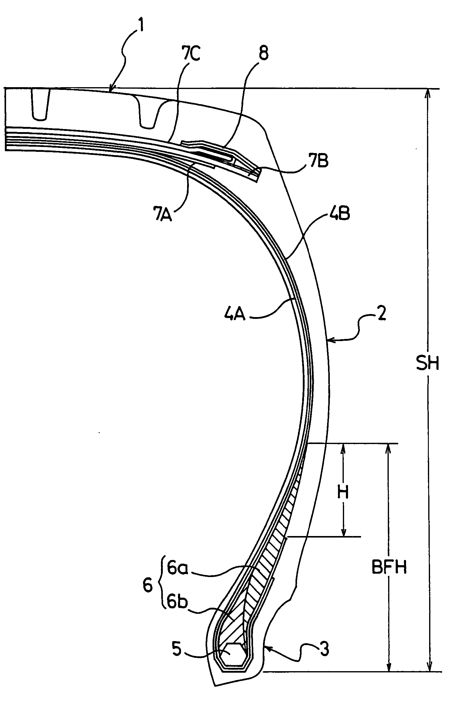
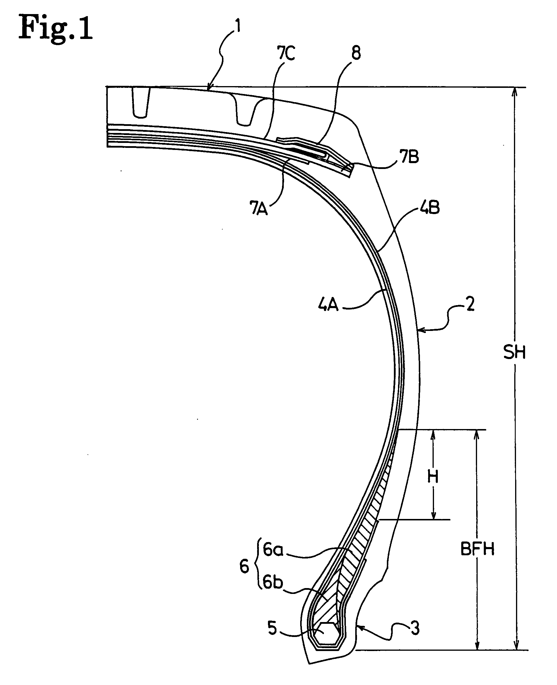
  • Summary
  • Abstract
  • Description
  • Claims
  • Application Information

AI Technical Summary

Benefits of technology

[0003] An object of this invention is to provide a pneumatic tire capable of enhancing durability and reducing rolling resistance while maintaining lateral stiffness.
[0005] As a result of having devotedly conducted a research on a pneumatic tire which is provided with a carcass ply formed of organic fiber cords and is used with a high internal pressure, the inventor of the present invention gained knowledge that: the pneumatic tire of this kind causes creep deformation in the carcass ply as a result of running and increases distortion in a belt edge portion, resulting in more likeliness of a separation failure in the belt edge portion in the last stage of abrasion. This knowledge has led the inventor to the present invention.
[0006] More specifically, in the present invention, by softening an apex portion of the bead filler based on configurations realized by (2) and (4), the lateral stiffness is maintained while distortion in the belt edge portion being reduced. At the same time, by ensuring the height of the bead filler based on a configuration realized by (3), the creep deformation in the carcass ply is suppressed. With these configurations, it becomes possible to enhance durability of the pneumatic tire which is provided with the carcass ply formed of organic fiber cords and is used with a high internal pressure. Additionally, by reducing heat generation of the apex portion of the bead filler based on configurations realized by (1) and (5), it becomes also possible to reduce rolling resistance thereof.
[0008] Additionally, it is preferred that: the number of the carcass plies be any one of one-layered structure and two-layered structure; all carcass plies be formed as a ply-lock structure where all of the carcass plies are turned up around the bead core from the inside of the tire to the outside; and the highest turned-up edge of the carcass plies be arranged more inwardly in the tire radial direction than the apex of the bead filler. The ply-lock structure here is intended to optimize stiffness of the bead portions and the sidewall portions of the pneumatic tire of the present invention. In particular, it is better that, in the tire radial direction, a distance between the highest turned-up edge of the carcass plies and the apex of the bead filler be at least 15 mm.

Problems solved by technology

While a pneumatic radial tire of this kind is used with a high air pressure and under a heavy loaded condition, the tire is required to be further improved in durability thereof since a separation failure in a belt edge portion thereof tends to occur in the last stage of abrasion.
Additionally, in the pneumatic radial tire of this kind, it is required that rolling resistance be reduced while maintaining lateral stiffness thereof which influences driving stability.

Method used


Image

  • Pneumatic Tire
  • Pneumatic Tire

Examples


examples

[0026] Tires of Examples 1 and 2 and Comparative Examples 1 to 6 were prepared as follows. In pneumatic radial tires for a light truck each of which a tire size is 195 / 75R15 and an air pressure corresponding to the maximum load capacity thereof is 600 kPa, a bead filler of each of the tires includes two different rubber layers stacked in a radial direction of the tire. In each of the pneumatic tires, a cross-sectional area S1, a hardness Hs1, a loss tangent tan δ1 of the rubber layer on the outermost side, and a cross-sectional area S2, a hardness Hs2, a loss tangent tan δ2 of the rubber layer on the innermost peripheral side, and a ratio of a height BFH of the bead filler to a cross-sectional height SH of the tire were set variously different from those in the other ones of the pneumatic tires. Additionally, for the purpose of comparison, a pneumatic radial tire for a light truck (Prior Art) was prepared, the pneumatic radial tire being provided with a bead filler constituted of on...


PUM


Abstract

Disclosed is a pneumatic tire capable of enhancing durability and reducing rolling resistance while maintaining lateral stiffness. The pneumatic tire of the present invention is provided with at least one carcass ply laid therein so as to extend between a pair of bead portions and formed of organic fiber cords. The tire has a casing structure where a bead filler is arranged to an outer periphery of a bead core buried in the bead portion. Additionally, an air pressure corresponding to the maximum load capacity of the tire is in a range from 350 to 650 kPa. The pneumatic tire is characterized in that the bead filler includes a plurality of rubber layers stacked in a radial direction of the tire, and a cross-sectional area S1, a hardness Hs1, and a loss tangent tan δ1 of the rubber layer on the outermost peripheral side; a cross-sectional area S2, a hardness Hs2, and a loss tangent tan δ2 of the rubber layer on the innermost peripheral side; and a ratio of a bead filler height BFH to a tire cross-sectional height SH are set to have the following relations (1) to (5): (S1×tan δ1) / [(S1×tan δ1)+(S2×tan δ2)]=0.25 to 0.40,  (1) (S1×Hs1) / [(S1×Hs1)+(S2×Hs2)]=0.35 to 0.50,  (2) BFH / SH=0.25 to 0.60,  (3) Hs2−Hs1=10 to 25, and  (4) tan δ1≦0.1 and tan δ2−tan δ1≦0.1  (5).

Description

TECHNICAL FIELD [0001] The present invention relates to a pneumatic tire suitable for a light truck and provided with a carcass ply formed of organic fiber cords. More specifically, the present invention relates to a pneumatic tire capable of enhancing durability and reducing rolling resistance while maintaining lateral stiffness. BACKGROUND ART [0002] As a pneumatic radial tire for a light truck, there is one including a carcass ply formed of organic fiber cords (for example, refer to Patent Document 1). While a pneumatic radial tire of this kind is used with a high air pressure and under a heavy loaded condition, the tire is required to be further improved in durability thereof since a separation failure in a belt edge portion thereof tends to occur in the last stage of abrasion. Additionally, in the pneumatic radial tire of this kind, it is required that rolling resistance be reduced while maintaining lateral stiffness thereof which influences driving stability. Patent Document ...

Claims


Application Information

Patent Timeline
Patent Type & Authority Applications(United States)
IPC IPC(8): B60C15/06
CPCB60C15/06B60C15/0607
Inventor WAKATSUKI, MASASHI
Owner THE YOKOHAMA RUBBER CO LTD
Learn More