
Pneumatic radial tire

a radial tire and pneumatic technology, applied in the field of pneumatic radial tires, can solve the problems of reducing the durability of the tire, reducing the durability of the belt layer, and reducing the elastic modulus of steel cords, so as to improve the resistance of the circumferential-direction reinforcement layer against fatigue rupture, and easing compressive strain

Active Publication Date: 2013-08-13
THE YOKOHAMA RUBBER CO LTD
View PDF26 Cites 3 Cited by
  • Summary
  • Abstract
  • Description
  • Claims
  • Application Information

AI Technical Summary

Benefits of technology

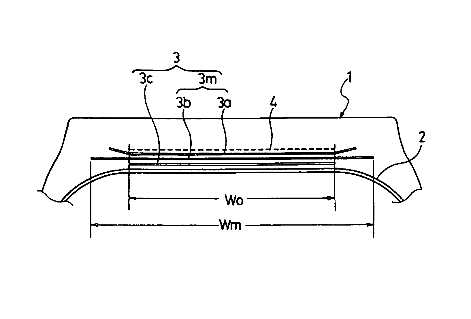
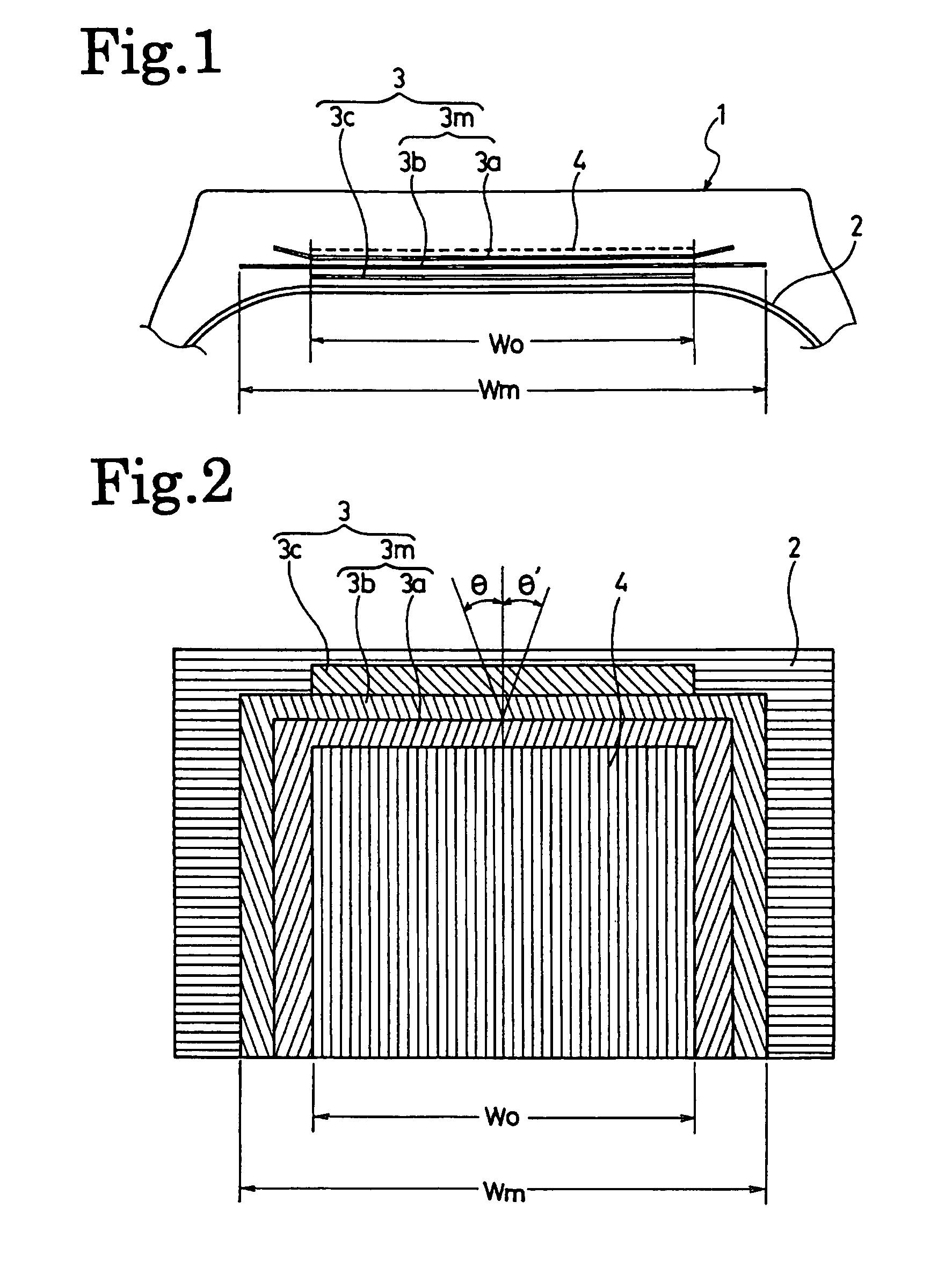
[0008]An object of the present invention is to provide a pneumatic radial tire, in which a main belt layer formed of steel cords and a circumferential-direction reinforcement layer formed of steel cords are disposed in the tread, and which has an improved fatigue resistance of the circumferential-direction reinforcement layer while the reinforcing effect of the circumferential-direction reinforcement layer to the main belt layer is secured.
[0009]Another object of the present invention is to provide a pneumatic radial tire, in which a main belt layer formed of steel cords and a circumferential-direction reinforcement layer formed of steel cords are disposed in the tread, and in which separation failure is prevented from occurring in the edge portions of the main belt layer, and also from occurring between the main belt layer and the circumferential-direction reinforcement layer.
[0012]According to the present invention, the width Wo of the circumferential-direction reinforcement layer in which steel cords are oriented in a substantial tire circumferential direction is restricted so as to have a certain relationship in size with the maximum width Wm of the main belt layer. At the same time, the reinforcement-cord elastic modulus Ee of the steel cords in the edge portions is set lower to a certain extent than the reinforcement-cord elastic modulus Ec of the steel cords in the center portion. Accordingly, it is possible to ease compressive strain in the edge portions while securing the reinforcing function of the circumferential-direction reinforcement layer as a tension member to the main belt layer. As a result, it is possible to improve the resistance of the circumferential-direction reinforcement layer against fatigue rupture.

Problems solved by technology

This leads to a problem that the durability of the belt layer is reduced.
However, steel cords have a high elastic modulus, and are thus vulnerable to compression.
In particular, there has been a problem that fatigue rupture is likely to occur in steel cords in the edge portions of the circumferential-direction reinforcement layer to thus reduce the durability of the tire.
A series of such phenomena make failure likely to occur in the edge portions of the circumferential-direction reinforcing layer.

Method used


Image

  • Pneumatic radial tire
  • Pneumatic radial tire

Examples


examples 1 to 3

, Conventional Example, and Comparative Examples 1 to 3

[0051]Seven types of heavy-duty pneumatic radial tires (Conventional Example, Examples 1 to 3, and Comparative Examples 1 to 3) were prepared under the same conditions that each tire had a tire size of 495 / 45R22.5 and the tire structure shown in FIG. 1, that the cord structure of steel cords used in the circumferential-direction reinforcement layer of each tire was 3×(1×0.34+6×0.30)HE, that the cross-sectional area of each cord was 1.54 mm2, and that the cord end count was 21 cords / 50 mm. On the other hand, these tires were made different from one another as described in Table 1 in the following factors: the reinforcement-cord elastic modulus Ec of the steel cords in the center portion of the circumferential-direction reinforcement layer; the reinforcement-cord elastic modulus Ee of the steel cords in the edge portions thereof; the ratio Wo / Wm of the width Wo of the circumferential-direction reinforcement layer to the maximum wi...

examples 4 to 8

[0063]Five types of heavy-duty pneumatic radial tires (Examples 4 to 8) were prepared under the same conditions as those of Example 1, which include the tire size, the tire structure, the cord structure of steel cords in the circumferential-direction reinforcement layer, the reinforcement-cord elastic modulus Ec of the steel cords in the center portion of the circumferential-direction reinforcement layer, the reinforcement-cord elastic modulus Ee of the steel cords in the edge portions thereof. Concurrently, these tires of Examples 4 to 8 were made different as described in Table 3, in the following factors: the ratio Wo / Wm of the width Wo of the circumferential-direction reinforcement layer to the maximum width Wm of the main belt layer; and the ratio Rc / Rs of the outer-peripheral-length change rate Rc of the tread portion on the equator to the outer-peripheral-length change rate Rs thereof on the shoulder portions.

[0064]The durability of each of these five types of the heavy-duty ...

examples 9 to 13

[0067]Three types of heavy-duty pneumatic radial tires (Examples 9 to 11) were prepared under the same conditions as those of Example 1, which include the tire size, the tire structure, the cord structure of steel cords in the circumferential-direction reinforcement layer, the reinforcement-cord elastic modulus Ec of the steel cords in the center portion of the circumferential-direction reinforcement layer, the reinforcement-cord elastic modulus Ee of the steel cords in the edge portions thereof. Concurrently, these tires of Examples 9 to 11 were made different as described in Table 4, in the following factors: the ratio Wo / Wm of the width Wo of the circumferential-direction reinforcement layer to the maximum width Wm of the main belt layer; and the ratio Rc / Rs of the outer-peripheral-length change rate Rc of the tread portion on the equator to the outer-peripheral-length change rate Rs thereof on the shoulder portions.

[0068]In addition, heavy-duty pneumatic radial tires (Examples 1...


PUM

PropertyMeasurementUnit
widthaaaaaaaaaa
pressureaaaaaaaaaa
inclination angleaaaaaaaaaa

Abstract

Provided is a pneumatic radial tire including a main belt layer and at least one circumferential-direction reinforcement layer, which are provided in the tread portion. The main belt layer includes two belt layers in which steel cords are disposed in a manner that the steel cords of a first one of the two belt layers intersect the steel cords of a second one of the two belt layers. In the circumferential-direction reinforcement layer, steel cords are disposed in a substantial tire circumferential direction. The ratio Wo / Wm of the width Wo of the circumferential-direction reinforcement layer to the maximum width Wm of the main belt layer is 0.5 to 0.9. The ratio Ee / Ec of the reinforcement-cord elastic modulus Ee of the steel cords in the edge portions of the circumferential-direction reinforcement layer to the reinforcement-cord elastic modulus Ec of the steel cords in the center portion of the circumferential-direction reinforcement layer is not less than (0.85−0.5 Wo / Wm) and not more than 0.8.

Description

TECHNICAL FIELD[0001]The present invention relates to a pneumatic radial tire. Specifically, the present invention relates to a pneumatic radial tire in which a main belt layer formed of steel cords and a circumferential-direction reinforcement layer formed of steel cords are disposed in the tread, and which has an improved fatigue resistance of the circumferential-direction reinforcement layer while the reinforcing effect of the circumferential-direction reinforcement layer to the main belt layer is secured.BACKGROUND ART[0002]In recent years, as to pneumatic radial tires for use in trucks and buses, it has been argued that dual tires be replaced with a single tire for the purpose of weight reduction and resource saving. The tread width of a single tire to be used instead of dual tires is increased while the outside diameter thereof is not changed, so that the aspect ratio of the tire is small. Accordingly, such a single tire is a so-called low-profile pneumatic radial tire. In add...

Claims


Application Information

Patent Timeline
Patent Type & Authority Patents(United States)
IPC IPC(8): B60C9/18B60C9/22B60C9/20
CPCB60C9/2006B60C9/28B60C2200/06Y10T152/10801Y10T152/1081Y10T152/10792Y10T152/10765B60C2009/2029
Inventor HARIKAE, SHINYA
Owner THE YOKOHAMA RUBBER CO LTD
Learn More