
Speaker

a speaker and speaker technology, applied in the field of speakers, can solve the problems of direct affecting the failure rate of the speaker in the drop test, and speaker failur

Active Publication Date: 2020-02-06
AAC TECH PTE LTD
View PDF0 Cites 1 Cited by
  • Summary
  • Abstract
  • Description
  • Claims
  • Application Information

AI Technical Summary

Benefits of technology

The present invention is a speaker that has a magnetic circuit system. It includes a first clamping plate, a yoke, a main magnetic, and a sub magnetic. The first clamping plate is bonded to the sub magnetic with an adhesive groove filled with glue. The bonding portion of the first clamping plate has an adhesive groove recessed from it. This design increases the contact area of the glue with the first clamping plate and improves the bonding force between them, solving a problem of small bonding force and separation failure in the drop test.

Problems solved by technology

Therefore, the solidity of the connection between the components used in the speaker directly affects the failure rate of the speaker in the drop test.
Wherein the sub magnetic is usually adhered to the first clamping plate by glue, and the width of the first clamping plate narrower than the sub magnetic, the region of bonding with the sub magnetic is small, thus the bonding force between the first clamping plate and the sub magnetic is small, so in the drop experiment, it is easy to make the first clamping plate and the sub magnetic of the speaker are detached, thereby, resulting in failure of the speaker.

Method used


Image

  • Speaker
  • Speaker
  • Speaker

Examples


embodiment 1

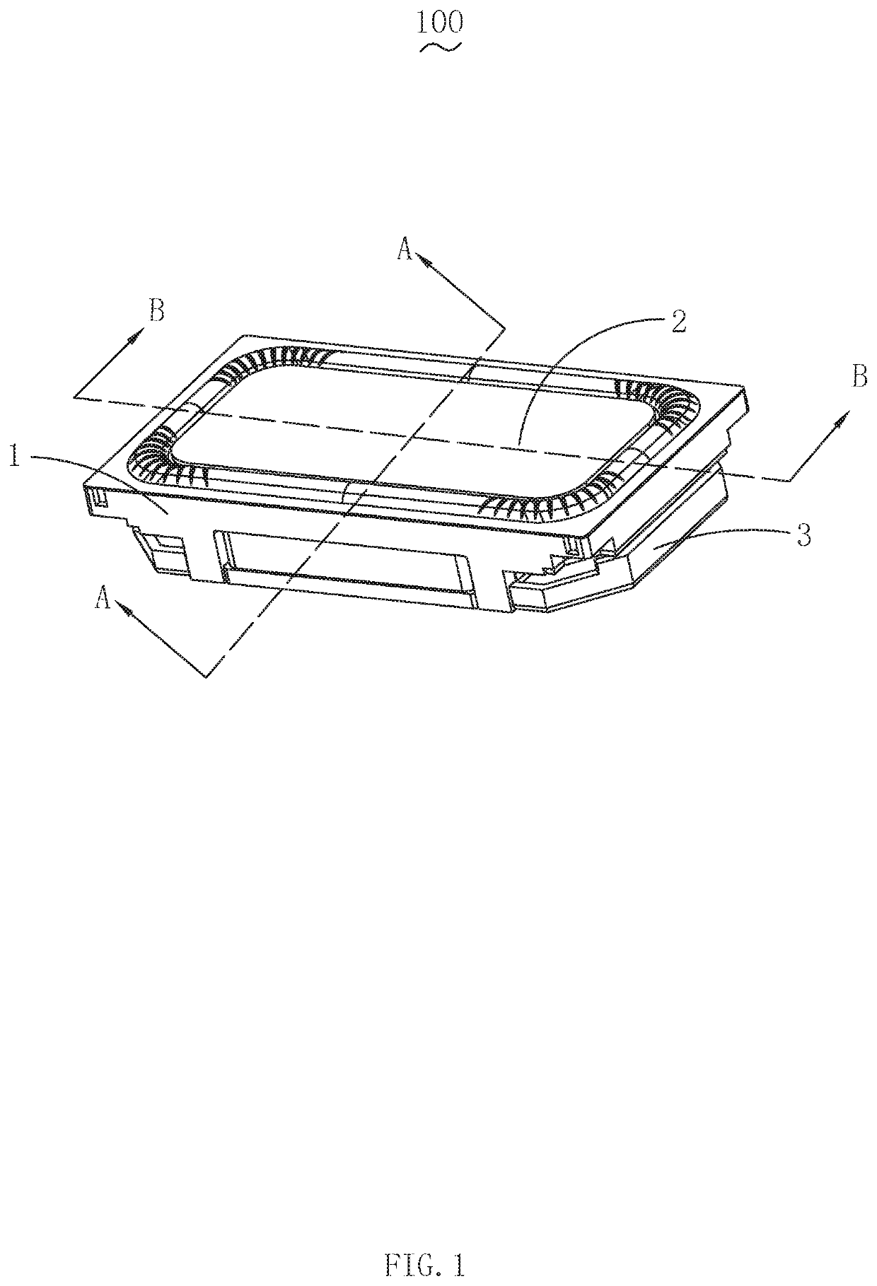
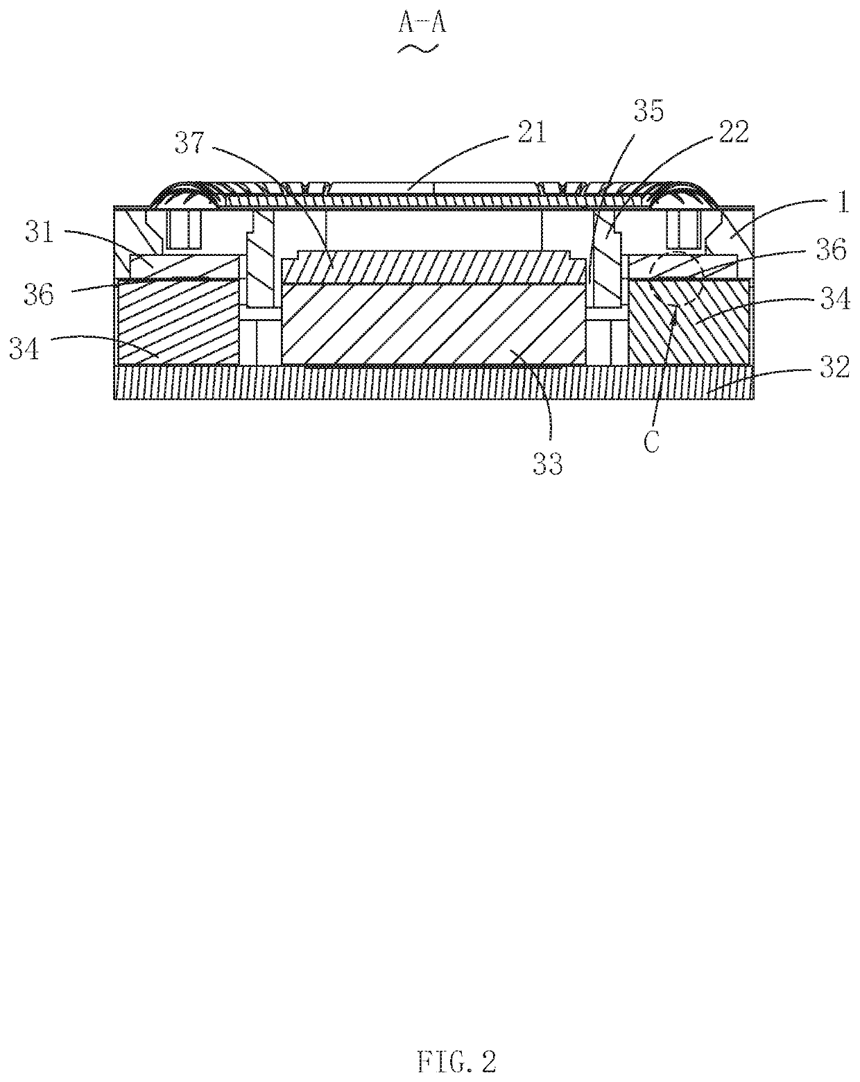
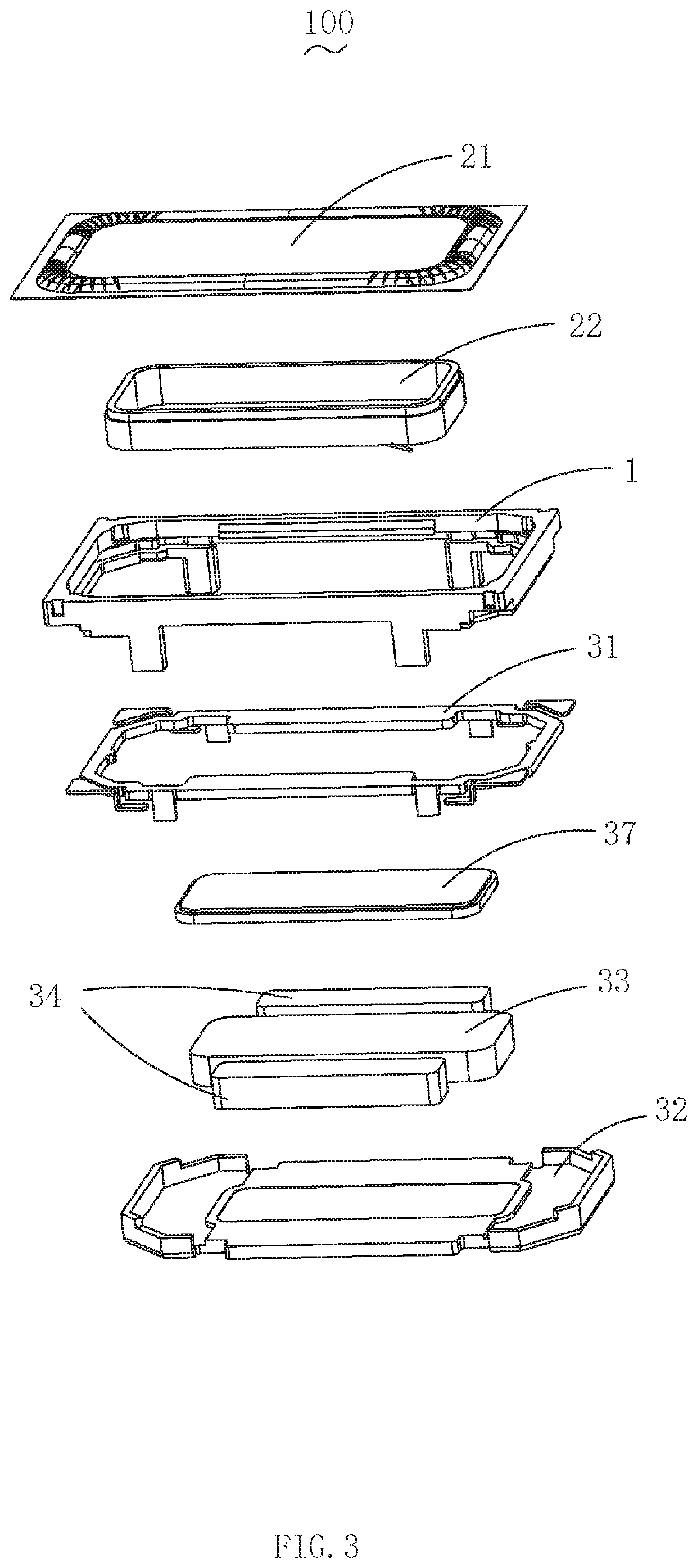
[0017]Please also refer to FIG. 1-3, wherein FIG. 1 is a three-dimensional diagram of structure of the speaker in accordance with an exemplary embodiment of the present disclosure; FIG. 2 is a cross-sectional diagram along the A-A line showing in FIG. 1; and FIG. 3 is a three-dimensional perspective diagram of the structure of the speaker exploded view showing in FIG. 1. The present disclosure provides a speaker 100, which comprises a frame 1, a vibration system 2 and a magnetic circuit system 3.

[0018]The vibration system 2 comprises a diaphragm 21 and voice coil assembly 22 driving the diaphragm 2 to vibrate for generating sound. The diaphragm 21 is located above the frame 1. The voice coil assembly 22 is connected to the diaphragm 21 and housed inside the frame 1. The magnetic circuit system 3 comprises a first clamping plate 31 housed in the frame 1, a yoke 32, a main magnetic 33 and a sub magnetic 34 disposed in the yoke 32. The sub magnetic 34 is located on both sides of the ma...

embodiment 2

[0020]As shown in FIG. 4, FIG. 4 is a plan view of the first clamping plate showing in the FIG. 1. The other features of the speaker provided in the embodiment 2 are the same as those in the embodiment 1, the difference is that the first clamping plate 31 further includes a splint frame 313, which is fixed to the frame 1.

[0021]It should be noted that the shape of the splint frame 313 is preferably the same as that of the yoke 32 edges around the circumference, but the shape of the splint frame 313 is any shape that can support the bonding portion 311 on the frame 1. The bonding portion 311 extends from the splint frame 313 in the direction toward the main magnetic 33. In the plane where the yoke 32 is located, the projection of the bonding portion 311 is completely coincides with the projection of the sub magnetic 34.

[0022]It should be pointed out that, on the basis of meeting the demand of miniaturization of the speaker, the width of the bonding portion 311 is set as wide as possib...

embodiment 3

[0024]Refer to FIG. 5, another speaker provided in this embodiment has the same features as Embodiment 2 except that the recessed depth H of the adhesive groove 312 is between 0.01 and 0.06 mm as shown in FIG. 5.

[0025]In the speaker of this embodiment, the recess depth H of the adhesive groove for accommodating the glue is preferably between 0.01 and 0.06 mm, and when the recess depth H of the adhesive groove is too large, the thickness of the adhesive body is larger, and the thick adhesive body is easy to break in the drop test; when the recessed depth H of the adhesive groove is too small, the contact area between the glue and the upper magnetic conductivity splint is insufficient to greatly improve the bonding force between the upper magnetic conductivity splint and the sub magnetic. The optimal anti-drop performance of the speaker can be achieved only when the depth of the depression is appropriate.


PUM


Abstract

The speaker of the present invention comprises a frame, a vibration system and a magnetic circuit system. The vibration system comprises a diaphragm and a voice coil assembly for driving the vibration of the diaphragm for generating sound, the diaphragm is located on the frame, and the voice coil assembly is connected with the diaphragm and the magnetic circuit system includes a first clamping plate, a yoke, and a main magnetic and a sub magnetic disposed in the yoke. Wherein the bonding portion of the first clamping plate and the sub magnetic is provided with an adhesive groove recessed from the bonding portion away from the sub magnetic. When the first clamping plate is bonded to the sub magnetic, the glue is filled between the first clamping plate and the sub magnetic and filled in the adhesive groove.

Description

FIELD OF THE DISCLOSURE[0001]The present disclosure relates to sound generator, and more particularly to a speaker applied in a portable electronic device.DESCRIPTION OF RELATED ART[0002]In order to adapt to the development trend of miniaturization and multi-function of various audio equipment and information communication equipment, the sound generator used in various equipment should be more miniaturized and more compact with other components around the sound generator.[0003]Especially with the development of mobile phones, the sound generator used therein requires not only miniaturization, but also excellent anti-drop performance.[0004]Therefore, the solidity of the connection between the components used in the speaker directly affects the failure rate of the speaker in the drop test.[0005]In related art, a speaker comprises frame, vibration system and magnetic circuit system. The vibration system comprises diaphragm and voice coil assembly driving the diaphragm to vibrate for ge...

Claims


Application Information

Patent Timeline
Patent Type & Authority Applications(United States)
IPC IPC(8): H04R9/06H04R9/02H04R7/16H04R7/12
CPCH04R7/12H04R2400/11H04R7/16H04R9/06H04R9/025H04R7/04H04R2499/11
Inventor LI, DENGLIN
Owner AAC TECH PTE LTD
Learn More