
Deposition Apparatus and Method for Manufacturing Organic Light Emitting Diode Display Using the Same

a technology of light-emitting diodes and manufacturing methods, which is applied in the direction of vacuum evaporation coatings, solid-state devices, coatings, etc., can solve the problems of difficult to obtain high-efficiency light emission, and achieve the effect of improving manufacturing yield, easy manufacturing process and increasing luminance uniformity for each pixel

Active Publication Date: 2013-12-05
SAMSUNG DISPLAY CO LTD
View PDF4 Cites 4 Cited by
  • Summary
  • Abstract
  • Description
  • Claims
  • Application Information

AI Technical Summary

Benefits of technology

This patent is about a method for depositing a material onto a substrate, which can improve the consistency and efficiency of the deposition. By controlling the angle at which the material is deposited, the method can ensure that the material is evenly distributed across the substrate, resulting in more consistent performance of each pixel in the display. Additionally, the method allows for easy replacement of the angle control member without stopping the process, which can improve manufacturing yield and efficiency. Overall, this patent provides a better way to deposit materials onto substrates and improve the quality of the finished product.

Problems solved by technology

However, in this structure, it is difficult to obtain high efficiency light emission so that a middle layer, such as an electron injection layer (EIL), an electron transport layer (ETL), a hole transport layer (HTL), and a hole injection layer (HIL), is selectively added and inserted between each electrode and the emission layer.

Method used


Image

  • Deposition Apparatus and Method for Manufacturing Organic Light Emitting Diode Display Using the Same
  • Deposition Apparatus and Method for Manufacturing Organic Light Emitting Diode Display Using the Same
  • Deposition Apparatus and Method for Manufacturing Organic Light Emitting Diode Display Using the Same

Examples


Embodiment Construction

[0029]A deposition apparatus and a method for manufacturing an organic light emitting diode (OLED) display according to embodiments of the present invention will be described with reference to the accompanying drawings. However, the present invention is not limited to the exemplary embodiments disclosed herein, but may be implemented in various different forms. The exemplary embodiments herein merely complete the disclosure of the present invention and fully provide an explanation of the invention to the person of ordinary skill in the art. Like reference numerals refer to like elements throughout the specification.

[0030]In the drawings, the thickness of layers, films, panels, regions, etc., are exaggerated for clarity. In the drawings, for better understanding and ease of description, the thicknesses of some layers and areas are exaggerated. It will be understood that, when an element such as a layer, film, region, or substrate is referred to as being “on” another element, it can b...


PUM

PropertyMeasurementUnit
angleaaaaaaaaaa
discharging direction angleaaaaaaaaaa
center anglesaaaaaaaaaa

Abstract

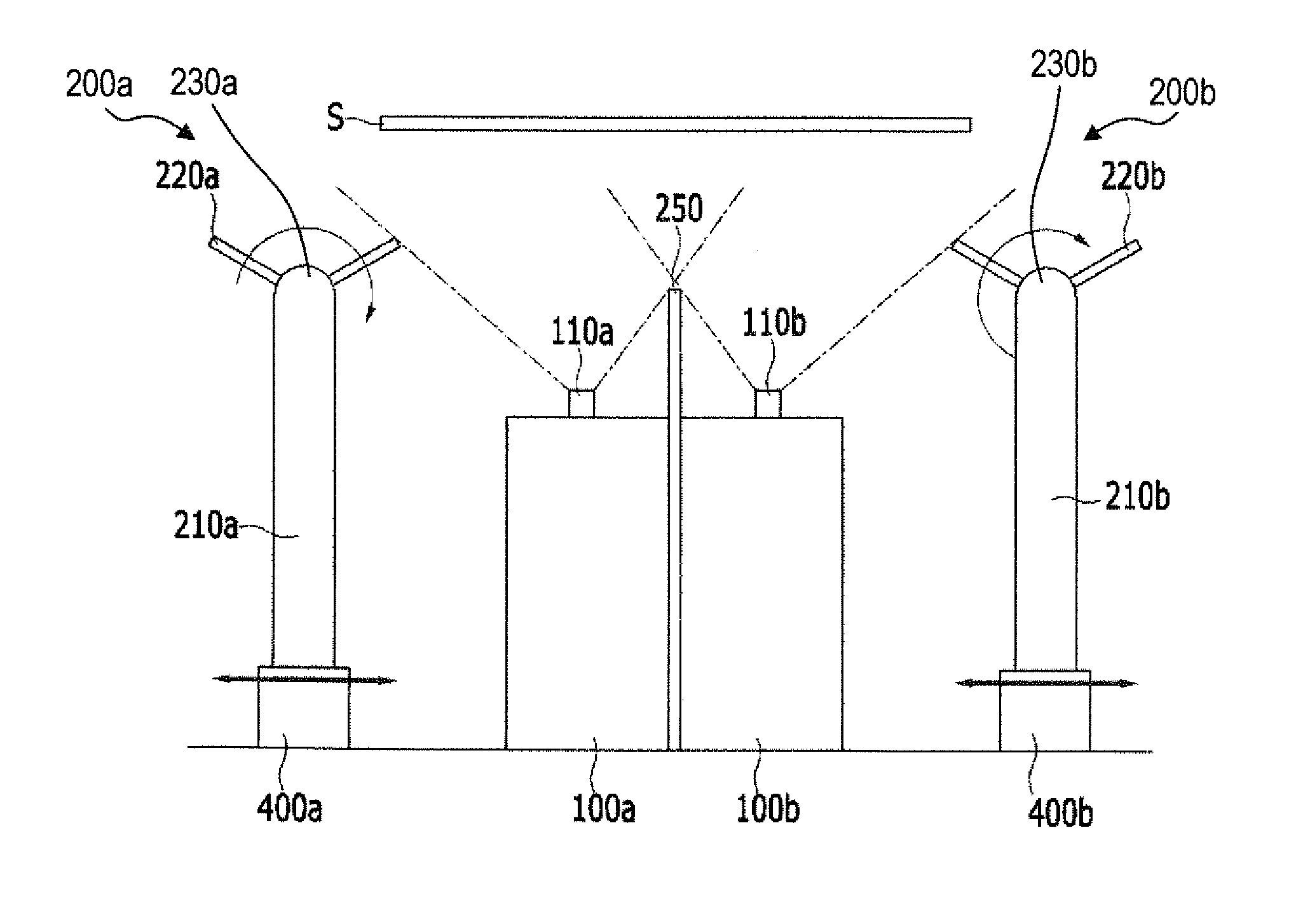
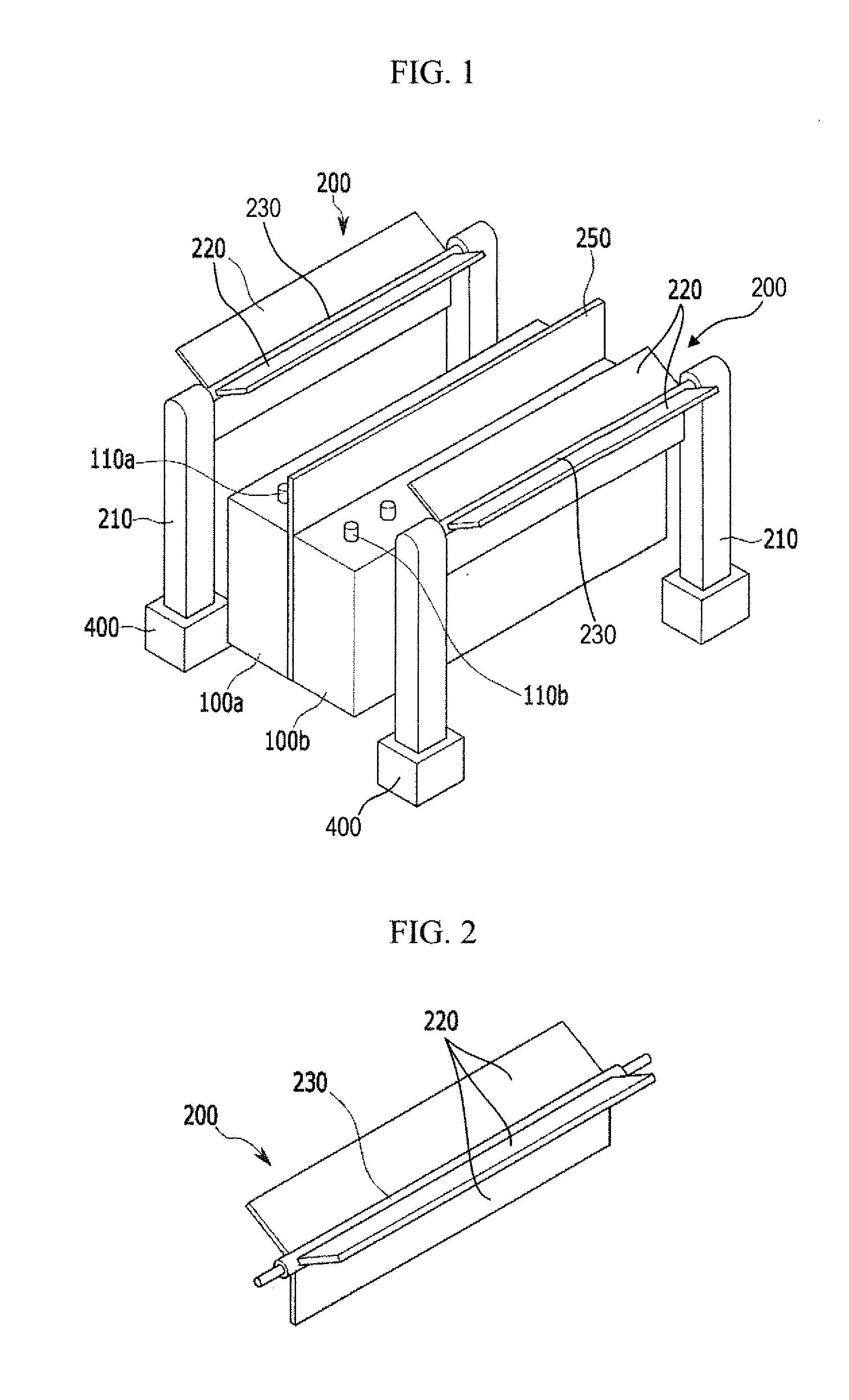
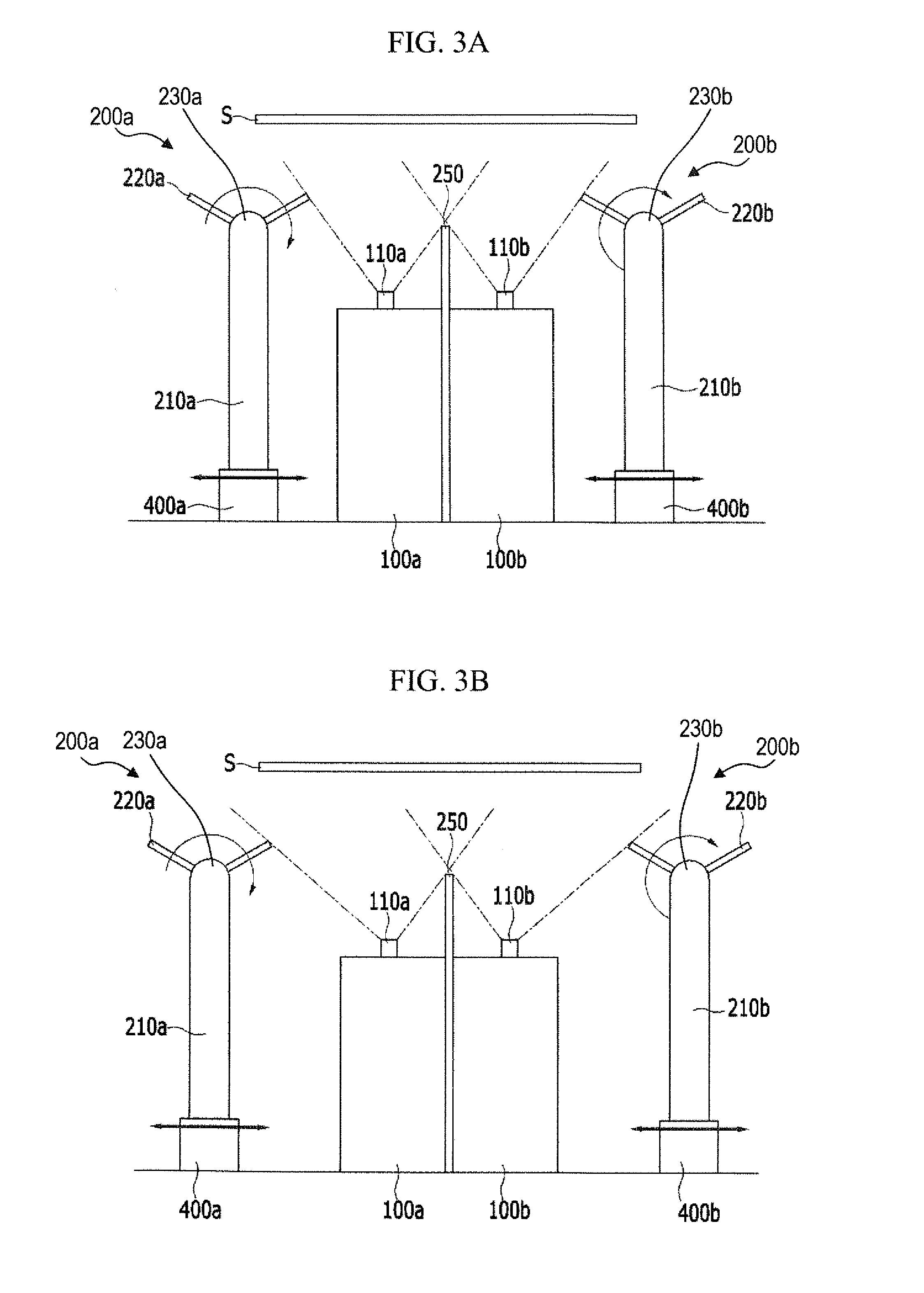
A deposition apparatus includes: a deposition source including a spray nozzle linearly arranged in a first direction and discharging a deposition material; and a pair of angle control members disposed at both sides of the deposition source and controlling a discharging direction angle of the deposition material. Each angle control member includes a rotation axis parallel to the first direction, and a plurality of shielding plates inst7lled about the rotation axis and separated from each other by a predetermined interval around the rotation axis. Although the deposition angle is changed according to the increasing of the process time, the deposition angle is compensated to form a uniform thin film. Also, the organic thin film may be uniformly deposited through each pixel of an organic light emitting diode (OLED) display, thereby increasing luminance uniformity for each pixel.

Description

CLAIM OF PRIORITY[0001]This application makes reference to, incorporates the same herein, and claims all benefits accruing under 35 U.S.C. §119 from an application earlier filed in the Korean Intellectual Property Office on the 31st of May 2012 and there duly assigned Serial No. 10-2012-0058418.BACKGROUND OF THE INVENTION[0002]1. Field of the Invention[0003]The present invention relates to a deposition apparatus and a manufacturing method of an organic light emitting diode (OLED) display using the same, and more specifically, to a deposition apparatus for controlling an emission direction of a deposition material by an angle control member, and a manufacturing method of an organic light emitting diode (OLED) display using the same.[0004]2. Description of the Related Art[0005]Among display devices, an organic light emitting diode display having the advantages of a wide viewing angle, excellent contrast, and a fast response speed has been receiving attention as one of the next generat...

Claims


Application Information

Patent Timeline
Patent Type & Authority Applications(United States)
IPC IPC(8): H01L51/56
CPCC23C14/044C23C14/22H10K71/12H10K71/441H10K71/164H10K71/00H01L21/6715
Inventor IM, JA-HYUNLEE, KWAN-HEEYOON, JI-HWANSIM, JOONG-WONSUNG, TAE-KWANG
Owner SAMSUNG DISPLAY CO LTD
Learn More