
Nano-porous electrode for super capacitor and manufacturing method thereof

a super capacitor and nanoporous technology, applied in the direction of electrolytic capacitors, electrotrophoretic coatings, coatings, etc., can solve the problems of reducing affecting the performance of the capacitor, so as to improve the specific surface area of the electrode, improve the energy density, power density, and the like of the capacitor, and increase the specific surface area

Active Publication Date: 2013-12-05
RES & BUSINESS FOUND SUNGKYUNKWAN UNIV
View PDF4 Cites 20 Cited by
  • Summary
  • Abstract
  • Description
  • Claims
  • Application Information

AI Technical Summary

Benefits of technology

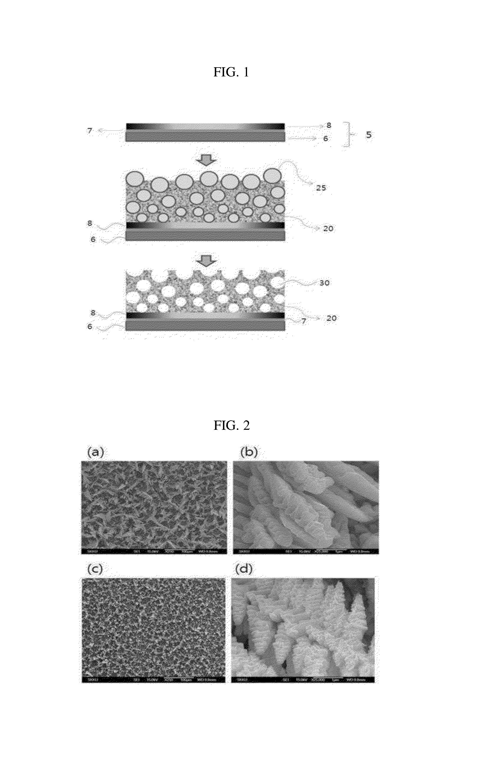
The present invention is about improving the performance of a super capacitor by using a nano-porous electrode that has a larger surface area. This results in increased charging and discharging capacity, as well as increased energy and power density of the capacitor. The method of manufacturing the electrode is also provided.

Problems solved by technology

However, in case of using such an aqueous electrolyte, there is a disadvantage in that the operating voltage of the aqueous electrolyte is limited to 1V, and thus the energy density of the capacity is also limited.
However, these alternative electrode materials have not yet exhibited the electrochemical characteristics corresponding to those of ruthenium oxide so far.
However, this pasting technique entails a problem in that a manufacturing process of carbon material-metal oxide composite electrode is a multi-staged process that is very complicated and requires a relatively long time, and in that the conductive material and the binder are indispensably used but these materials are not actually involved in the electrochemical reaction exhibiting the specific capacitance of the electrode.
However, these Japanese patent documents suffer from a drawback in that since the plating is performed on the matrix formed with pores to manufacture the electrode for a capacitor, there is a limitation in the specific surface area of the electrode and the control of the specific surface area is impossible.

Method used


Image

  • Nano-porous electrode for super capacitor and manufacturing method thereof
  • Nano-porous electrode for super capacitor and manufacturing method thereof
  • Nano-porous electrode for super capacitor and manufacturing method thereof

Examples


example 1

Manufacture of Nano-Porous Electrode Using Manganese Oxide and Alloy

[0065]A titanium layer was formed into a thickness of 10 nm on a silicone matrix by sputtering titanium. Thereafter, a conductive platinum substrate in which a platinum layer was formed into a thickness of 200 nm on the titanium layer by sputtering titanium was used as a conductive metal matrix.

[0066]The conductive platinum substrate was used as a working electrode and the platinum plate was used as a counter electrode to form a porous manganese-containing structure on the manufactured conductive platinum substrate. A distance between a cathode and an anode was maintained to be 2 cm, and an Ag / AgCl reference electrode was used. In addition, MnSO4.H2O, and NH4Cl were contained as an electrolyte. In this case, concentrations of the electrolytes were 0.2M MnSO4.H2O, and 1M NH4Cl, respectively, and copper and tin were added thereto at a concentration of 0.01M. The conductive platinum substrate was immersed in 20 ml of t...

example 2

Manufacture of Nano-Porous Electrode Using Nickel Oxide and Alloy

[0067]The conductive platinum substrate was used as a working electrode and the platinum plate was used as a counter electrode to form a porous nickel-containing structure on the conductive platinum substrate manufactured in Example 1. In this case, a distance between a cathode and an anode was maintained to be 2 cm, and an Ag / AgCl reference electrode was used. In addition, NiCl2.6H2O, SnCl2.2H2O, and H2SO4 were contained as an electrolyte. In this case, a concentration of the electrolyte was 0.2M NiCl2.6H2O, 0.01M SnCl2.2H2O, and 1M H2SO4, respectively. The conductive platinum substrate was immersed in 20 ml of the prepared electrolyte, and electrodeposition was performed on the conductive platinum substrate for 1 minute by applying a voltage of −3 volt across the conductive platinum substrate to deposit a porous nickel / tin structure on the conductive platinum substrate, thereby manufacturing a porous nickel / tin elect...

example 3

Manufacture of Nano-Porous Electrode Using Cobalt Oxide and Alloy

[0068]The manufacture of the nano-porous electrode in Example 3 was performed in the same method as that in Example 2 except the following process. CoSO4.2H2O, SnCl2.2H2O and H2SO4 were contained as an electrolyte. In this case, concentrations of the electrolytes were 0.2M CoSO4.2H2O, 0.2M SnCl2.2H2O, and 1M H2SO4, respectively. A porous electrode formed with a porous cobalt / tin structure was manufactured. An annealing (oxidation) process was performed on the manufactured porous cobalt / tin electrode at 300° C. As a result, it could be found that a porous cobalt / tin structure was formed as shown in FIG. 4(a), and the porous cobalt / tin structure was formed as a number of dendritic structures of a protrusion shape as shown in FIG. 4(b).


PUM

PropertyMeasurementUnit
Thicknessaaaaaaaaaa
Thicknessaaaaaaaaaa
Thicknessaaaaaaaaaa

Abstract

The present invention relates to a nano-porous electrode for a super capacitor and a manufacturing method thereof, and more specifically, to a nano-porous electrode for a super capacitor and a manufacturing method thereof wherein pores are formed on the surface or inside an electrode using an electrodeposition method accompanied by hydrogen generation, thereby increasing the specific surface area of the electrode and thus improving the charging and discharging capacity, energy density, output density, and the like of a capacitor. The method for manufacturing a nano-porous electrode for a super capacitor according to the present invention manufactures a nano-porous electrode using hydrogen generated by the electrodeposition as a template to minimize the amount of metal used, so that electrode manufacturing costs can be sharply reduced, the specific surface area of the electrode can be adjusted by a simple process, and also the charging and discharging capacity, energy density, output density, and the like of a capacitor can be improved by increasing the specific surface area.

Description

TECHNICAL FIELD[0001]The present invention relates to a nano-porous electrode for a super capacitor and a manufacturing method thereof, and more specifically, to a nano-porous electrode for a super capacitor and a manufacturing method thereof wherein pores are formed on the surface of or inside an electrode using an electrodeposition method accompanied by hydrogen generation, thereby increasing the specific surface area of the electrode and thus improving the charging and discharging capacity, energy density, power density of a capacitor, and the like.BACKGROUND ART[0002]In general, a high-performance portable power supply has been used as a main component of end-products essentially used in all portable information communication equipment, electronic apparatus, electric automobiles and so on. Next generation energy storage systems, which are recently developed, utilize electrochemical principles and are exemplified by a Li based secondary cell and an electrochemical capacitor.[0003...

Claims


Application Information

Patent Timeline
IPC IPC(8): H01G11/26H01G11/24
CPCH01G11/26C25D1/16C25D5/48C25D13/02C25D13/22H01G11/24Y02E60/13
Inventor CHUNG, CHANHWAJEONG, MYUNG GICHEREVKO, SERHIY
Owner RES & BUSINESS FOUND SUNGKYUNKWAN UNIV
Learn More