
Electric automobile

a technology of electric vehicles and motors, applied in the direction of motors/generators/converter stoppers, dynamo-electric converter control, instruments, etc., can solve the problems of constant external vibration, significant fluctuations in the rotational frequency of motors and/or current flow in motor coils, and the inability of motors mounted to in-wheel electric vehicles to operate. achieve the effect of vehicle travel safety, increase in the temperature of motors, and high torqu

Inactive Publication Date: 2013-12-05
NTN CORP
View PDF26 Cites 26 Cited by
  • Summary
  • Abstract
  • Description
  • Claims
  • Application Information

AI Technical Summary

Benefits of technology

The patent text discusses how the driving conditions of an electric vehicle can affect the motor's rotational frequency and current flow, leading to temperature fluctuations that can affect motor insulation and travel safety. The technical effect of the patent is to provide a solution for managing the temperature of the motor to ensure the vehicle travels safely and efficiently.

Problems solved by technology

The driving conditions of an electric vehicle may constantly change, resulting in significant fluctuations of the rotational frequency of a motor and / or the current flow in motor coils.
A motor mounted to an in-wheel electric vehicle may have to operate in a severe environment.
For example, such a motor may be constantly subject to externally-induced vibrations because it is positioned below suspension springs or it is unsprung.
This leads to increase in the temperature of a motor, possibly deteriorating the insulation on the motor coils.
In such a case, an inverter may cause overheat by conducting a large current.
This may undesirably change the characteristics of the inverter and / or even damage the inverter.
This, in turn, may lead to undesirable change in the control characteristics of the driving of a motor and / or lead to a situation where the driving of a motor is impossible.
Such a configuration, however, may drastically hinder the driving of a vehicle.

Method used


Image

  • Electric automobile
  • Electric automobile
  • Electric automobile

Examples


first embodiment

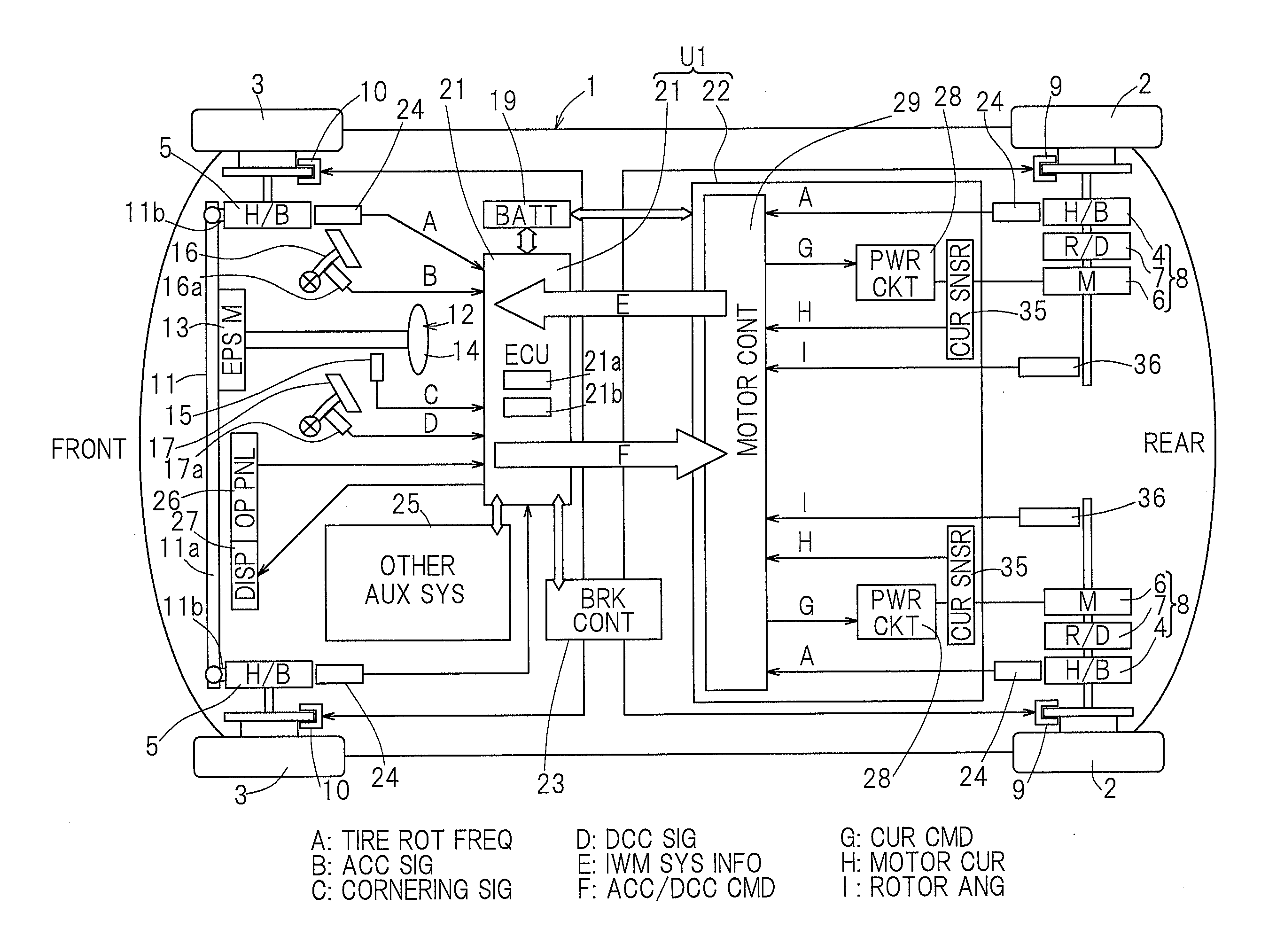
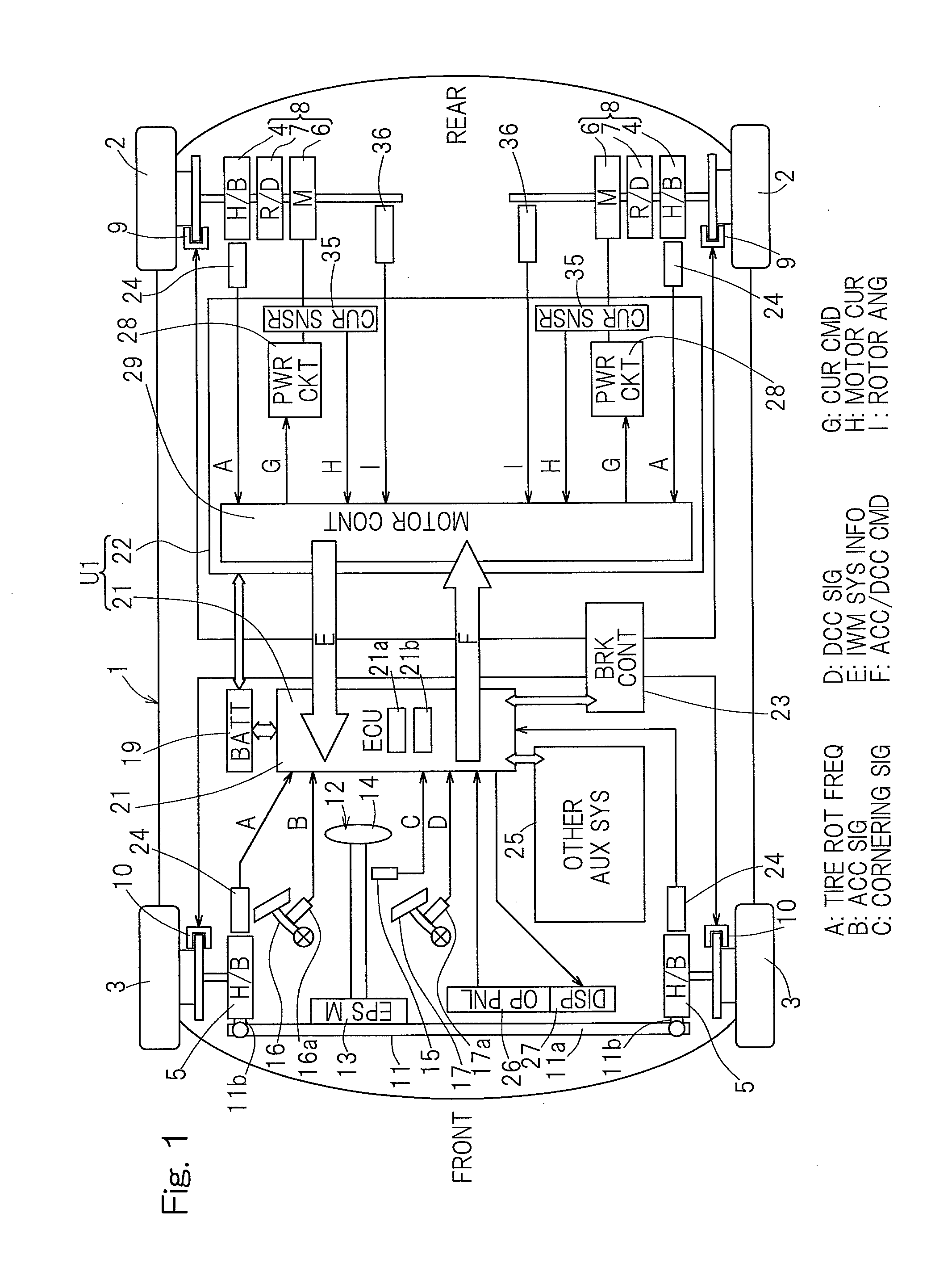
[0043]An electric vehicle according to the present invention will now be described in connection with FIG. 1 to FIG. 8. The illustrated electric vehicle is a four-wheel vehicle that includes a vehicle body 1 with left and right rear wheels 2 and left and right front wheels 3, with the rear wheels 2 being drive wheels and the front wheels 3 being steered driven wheels. The drive wheels 2 and the driven wheels 3, both equipped with tires, are supported by the vehicle body 1 via respective wheel bearing units 4, 5. In FIG. 1, the wheel bearing units 4, 5 are labeled with “H / B” which is an abbreviation for hub bearing. The left and right drive wheels 2, 2 are driven by respective independent traction motor units 6, 6. Rotation of a motor unit 6 is transmitted via a reducer unit 7 and a wheel bearing unit 4 to a wheel 2. The motor unit 6, the reducer unit 7 and the wheel bearing unit 4 are integrally assembled with each other to form an in-wheel motor drive system 8 that is partly or ent...

second embodiment

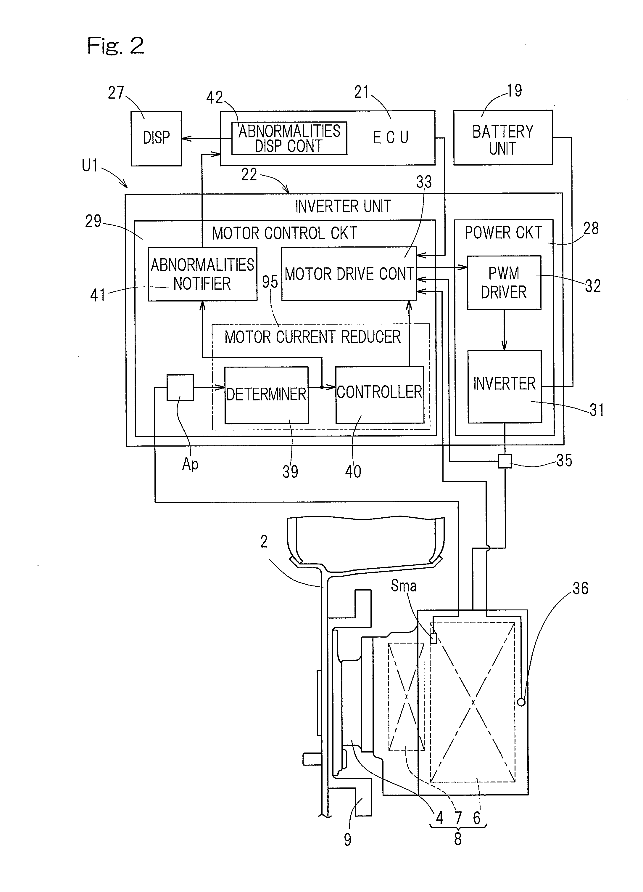
[0082]The motor current of the motor unit 6 may be reduced by a predefined proportion. For example, the motor current of the motor unit 6 may be reduced, after every certain period of time, by a certain percentage relative to the original motor current. For another example, the proportion by which the motor current of the motor unit may be reduced may, after every certain period of time, be incremented. As shown in FIG. 9 which illustrates an electric vehicle the ECU 21 which is an electronic control unit configured to perform general control of the vehicle may include the motor current reducer 95.

[0083]An electric vehicle according to the third embodiment and the fourth embodiment of the present invention will be discussed below. Note that those features corresponding to the features already described with reference to the preceding embodiment(s) will be given the same reference signs and will not be described. In the discussion of a given configuration where only certain features...

third embodiment

[0084]Referring to the block diagram of FIG. 10, a schematic configuration of several features including an inverter unit, of an electric vehicle according to the present invention will now be described. In the embodiment under discussion, the motor control circuitry 29 may include an inverter limiter 102, which will be described below, as well as an abnormalities notifier 41, and the ECU 21 may include an abnormalities display controller 42. Furthermore, a temperature sensor Sia may be associated with the inverter 31, which is configured to sense temperature Tic of the inverter 31. The inverter limiter 102 may limit a current command to the inverter 31. The inverter limiter 102 may, upon determining that the temperature Tic of the inverter 31 sensed by the temperature sensor Sia exceeds a predefined inverter temperature threshold, limit a current command to the inverter 31 until a derivative dTic / dt of the sensed temperature Tic with time t drops to zero or below. In particular, th...


PUM


Abstract

An electric vehicle includes a motor unit to drive a wheel. The electric vehicle also includes a control system that controls the motor unit. The control system includes an inverter. The electric vehicle also includes a temperature sensor to sense temperature Tmc of the motor coils of the motor unit or a temperature sensor to sense temperature Tic of the inverter. The electric vehicle also includes a limiter to, if the temperature Tmc sensed by the sensor exceeds a motor coils temperature threshold, reduce a motor current of the unit until a derivative dTmc / dt of the sensed temperature Tmc with time t drops to zero or below, or to, if the temperature Tic sensed by the sensor exceeds an inverter temperature threshold, limit a current command to the inverter until a derivative dTic / dt of the sensed temperature Tic with time t drops to zero or below.

Description

[0001]CROSS REFERENCE TO THE RELATED APPLICATIONS[0002]This application is based on and claims the Convention priority to Japanese patent applications No. 2011-039854 and No. 2011-039855, both filed Feb. 25, 2011, the entire disclosures of which are herein incorporated by reference as a part of this application.BACKGROUND OF THE INVENTION[0003]1. Field of the Invention[0004]The present invention relates to an electric vehicle, such as an in-wheel motor vehicle, that is equipped with motor(s) to drive wheels and that may be battery-powered or fuel cell-powered.[0005]2. Description of Related Art[0006]An electric vehicle may experience degradation in performance or malfunctions of a motor serving as a drive for the vehicle. This can significantly affect the travel performance or travel safety. A battery-powered electric vehicle may include a drive system. The drive system may employ an IPM (e.g., Interior Permanent Magnet synchronous motor). Such an IPM may include a neodymium magnet ...

Claims


Application Information

Patent Timeline
IPC IPC(8): H02P29/00B60K7/00
CPCH02P29/0055H02P29/0088B60K7/0007B60L3/0061B60L2240/425H02P29/64B60L50/51B60L3/06H02P6/28H02P29/032B60L1/003B60L3/003B60L3/12B60L15/025B60L15/2009B60L15/2036B60L15/2054B60L2220/14B60L2220/46B60L2220/50B60L2240/12B60L2240/24B60L2240/34B60L2240/36B60L2240/421B60L2240/423B60L2240/429B60L2240/461B60L2250/16B60L2250/26B60L2260/28B60L2270/145Y02T10/64Y02T10/70Y02T10/72B60L58/12
Inventor OZAKI, TAKAYOSHI
Owner NTN CORP
Learn More