Method for forming an end-side toothing arrangement

a technology of end-side teeth and toothing, which is applied in the direction of bearings, couplings, basic electric elements, etc., can solve the problems of not always having a sufficiently precise fit and obvious limit of the rivet head method

Active Publication Date: 2013-12-05
SCHAEFFLER TECH AG & CO KG
View PDF4 Cites 0 Cited by
  • Summary
  • Abstract
  • Description
  • Claims
  • Application Information

AI Technical Summary

Benefits of technology

[0014]The die is an instrument which is used in a template-like manner in the sense of a delimitation in order to restrict radial expansion during the cold reshaping. As a result, the material flow of the rolling rivet collar is diverted in an intensified manner in the axial direction during the cold reshaping. The shaping by the rivet header, the force exerted by which is opposed to the flow of material, is thus much more effective. The teeth of the end-side toothing arrangement can be shaped more precisely. Even shapes which cannot be achieved without a die, for example a greater axial tooth height, are possible.
[0015]Advantageously, the die shapes an axial and / or radial outer face of the rolling rivet collar. In addition to the function of the radial delimitation by the die, the die can also be used for shaping the rolling rivet collar. This may for example be the case on the cylindrical outer face, or else in an axial outer face of the rolling rivet collar. It is thus possible to achieve very extensive design freedom and to use this freedom advantageously for a desired shape of the rolling rivet collar. The die and the rivet header can interact in such a way that the desired material flow occurs. The result becomes all the more dimensionally precise when the die and the rivet header can be used to control any possible spread of the loss of material and the deformation pressure acting on the rolling rivet collar as it forms is increased.
[0017]Advantageously, a clamping ring radially supports the inner ring of the rolling bearing from the outside inwards during the reshaping (second step). A clamping ring of this type prevents the disadvantageous widening of the inner ring in the radial direction during the rivet heading.
[0022]Advantageously, the circumferentially continuing embossment is embodied as an encoder. This fulfills a component integration which is very efficient in terms of manufacture and leads to a stable transmitter wheel. Normally, encoders have to be used as a separate component requiring a separate manufacturing step, This step is now no longer necessary. In addition, the encoder cannot move axially away from the sensor of a rotational speed measuring device. This ensures a very reliable measurement of rotational speed.

Problems solved by technology

However, the limits of the rivet heading method become apparent when a large number of thin teeth having a large tooth depth have to be produced.
Furthermore, it has in practice been found that the rivet heading method often leads to an unevenly shaped end-side toothing arrangement in which the engagement with the mating toothing arrangement does not always have a sufficiently precise fit for uniform torque transmission.

Method used


Image

  • Method for forming an end-side toothing arrangement
  • Method for forming an end-side toothing arrangement
  • Method for forming an end-side toothing arrangement

Examples


Embodiment Construction

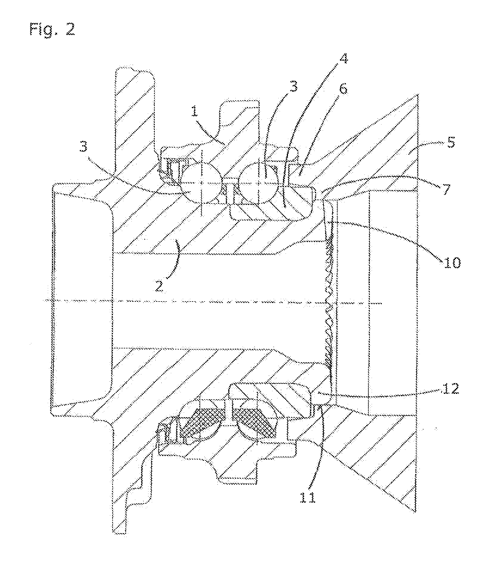
[0028]FIG. 1 is a longitudinal section of a third-generation preassembled wheel bearing unit with a die 5 before the rolling riveting process in a first step of the method for forming an end-side toothing arrangement.

[0029]The deformable, cylindrical end piece 9 of the wheel hub 2 is to be cold reshaped in the pending rolling riveting process. For this purpose, the die 5 is arranged on the preassembled wheel bearing unit in such a way that a molding face 8 of the inner extension 7 can be used for radially delimiting and shaping the rolling rivet collar. The molding face 8 is cylindrical, allowing a likewise cylindrical shape to be imparted to the roiling rivet collar. However, the molding face 8 could also be configured conically for the purpose of better shaping.

[0030]The inner extension 7 is designed in one piece with the die 5, so that the method can be kept easy to carry out.

[0031]Advantageously, the damping ring 6 is also formed in one piece with the die 5 and conically embodie...


PUM

PropertyMeasurementUnit
torqueaaaaaaaaaa
depthaaaaaaaaaa
surface areaaaaaaaaaaa

Abstract

In summary, the invention relates to a method for forming an end-side toothing arrangement of a roiling bearing, in particular a wheel bearing. The aim is to improve the uniformity of the end-side toothing arrangement and to allow a greater tooth depth. This is achieved by two method steps in that, in a first step before the reshaping of an end piece of a hub, a die is axially arranged on the rolling bearing in a preassembled state and, in a second step during the reshaping of the end piece and the shaping of the end-side toothing arrangement, the die radially delimits a radial recess of the rolling rivet collar as it forms. In addition, the die reduces or prevents radial widening of the inner ring.

Description

CROSS REFERENCE TO RELATED APPLICATIONS[0001]This application is a divisional application of U.S. patent application Ser. No. 12 / 789,118, filed May 27, 2010, which darns priority of DE 10 2009 023 042.4, filed May 28, 2009, Both applications are incorporated herein by reference.FIELD OF THE INVENTION[0002]The invention relates to a method for forming an end-side toothing arrangement from a rolling rivet collar of a rolling bearing, in particular a wheel bearing. The invention further relates to a rolling bearing, or wheel bearing, with a correspondingly molded-on end-side toothing arrangement.BACKGROUND OF THE INVENTION[0003]A method of this type is used in particular in the automotive field in the manufacture of wheel bearings.[0004]In the past, it has been found that a wheel bearing, but also other rolling bearings with a rolling rivet collar, can advantageously be connected to the driving element of the drive train via an end-side toothing arrangement in order to save installatio...

Claims


Application Information

Patent Timeline
Patent Type & Authority Applications(United States)
IPC IPC(8): F16C43/04
CPCF16C43/04B21K1/30F16C19/186F16C33/605F16D1/076F16C2326/02Y10T29/4968Y10T29/49535Y10T29/49696Y10T29/497Y10T29/49679Y10T29/49643
Inventor LANGER, ROLANDNIEBLING, PETERLORENZ, SEBASTIAN
Owner SCHAEFFLER TECH AG & CO KG
Why Eureka
Try Eureka