Power Generating Windbags and Waterbags

Active Publication Date: 2013-11-21
SIA YIK HEI
View PDF28 Cites 51 Cited by
  • Summary
  • Abstract
  • Description
  • Claims
  • Application Information

AI Technical Summary

Benefits of technology

The present invention is a method, system, and apparatus for generating electrical power using a power-bag mounted on a mobile navigable vehicle body. The vehicle body pulls a tether through a drive unit, which powers an electricity generation module. The power-bag captures and entraps motive fluid, such as wind and water, as it moves along in the linear direction of the fluid. The invention can be used in a variety of terrains and environments, from surface to high altitude and from sea to sea. The invention maximizes the use of the fluid's energy by using a wire-guided bag system and a large empty cavity to capture and entrap the moving air. The airborne platform for the bags includes a specialized equipment such as HAV-45 and the UAS infrastructure. The invention provides a more efficient and cost-effective way to generate energy from wind and water.

Problems solved by technology

However, some devices like: wind mills, wind turbines, water wheels may be deficient and self-limiting due to (i) the minimized surface area for capture of the kinetic energy of the fluid medium as evidenced by the limited size and number of turbine blades, rotors, propellers, spokes; sails, etc. that may be affixed to an apparatus; (ii) the extremely short, momentary, contact time between the drive surface and the moving fluid medium providing the kinetic energy lasting a few seconds; and (iii) harnessing the kinetic energy in an ad-hoc randomized manner.
But in actual fact the bag does not fly; in the real sense of the word “flying” because it is not capable of generating aerodynamic lift.
The airborne windbags system of power generation is more complicated and entails more expensive customized equipment comprising of the UAS infrastructure such as: Hybrid Aerial Vehicles HAV-100, “Morphing Bag-crafts 90,” etc. than the parallel seaborne water-bags system of power generation.

Method used


Image

  • Power Generating Windbags and Waterbags
  • Power Generating Windbags and Waterbags
  • Power Generating Windbags and Waterbags

Examples


Embodiment Construction

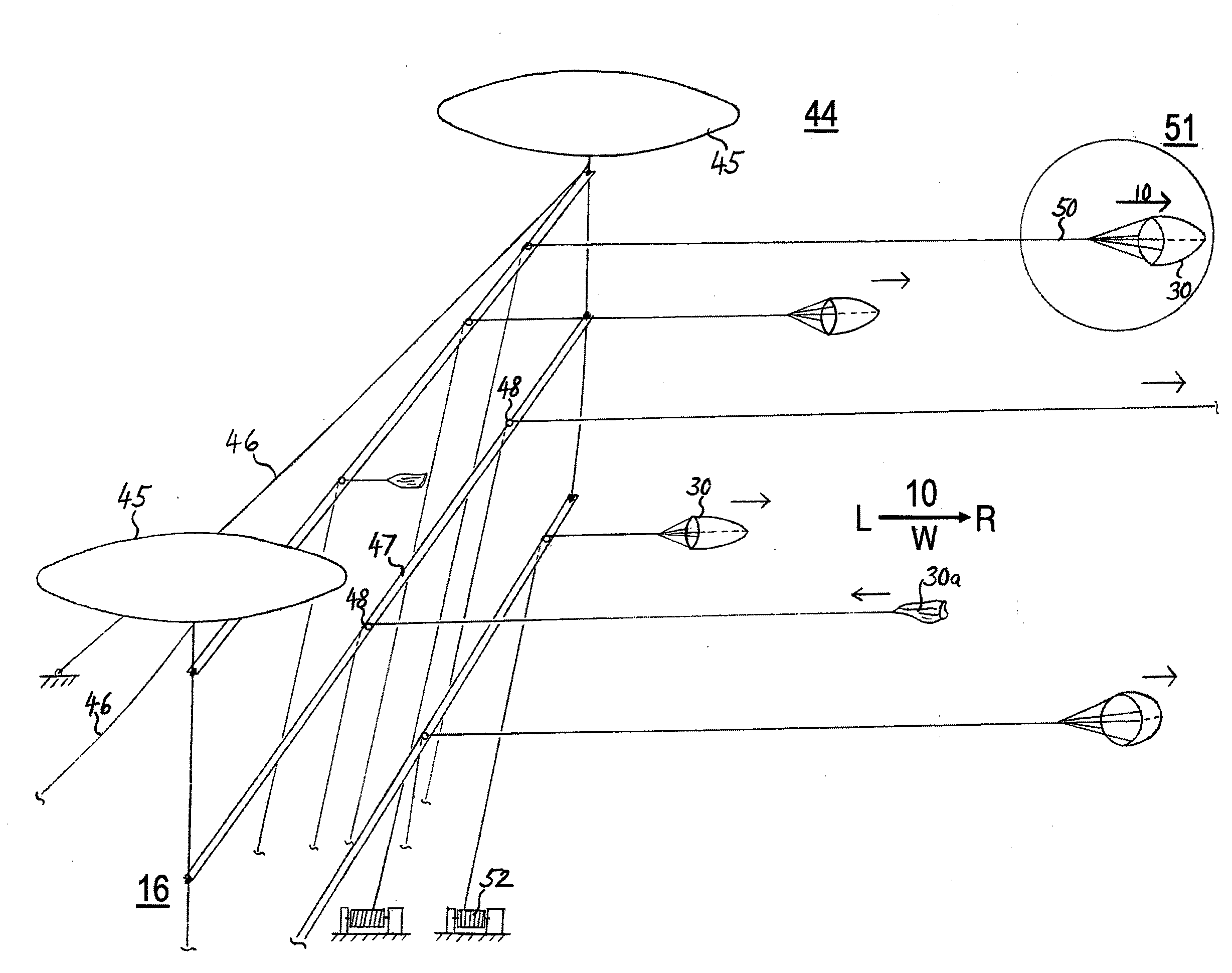
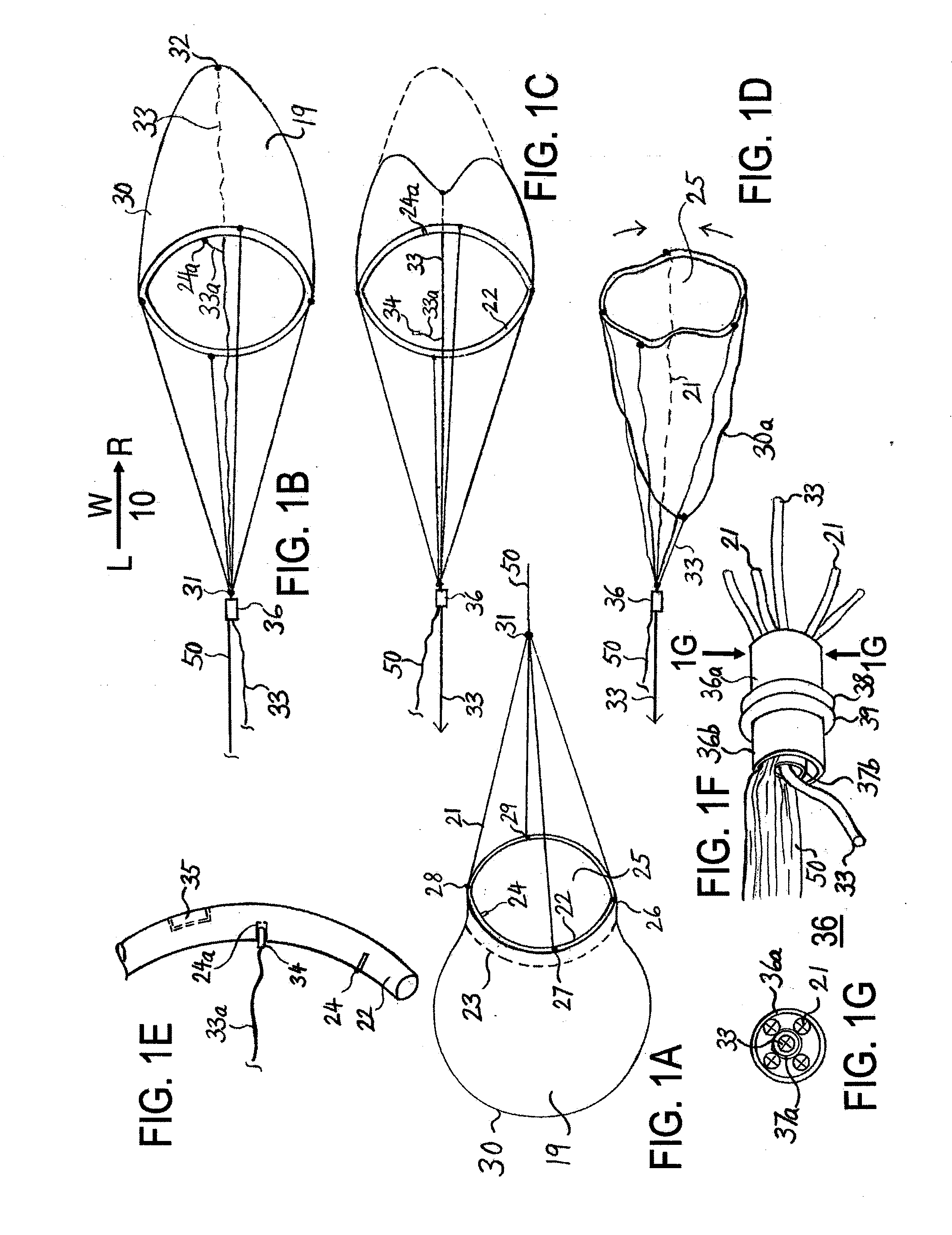
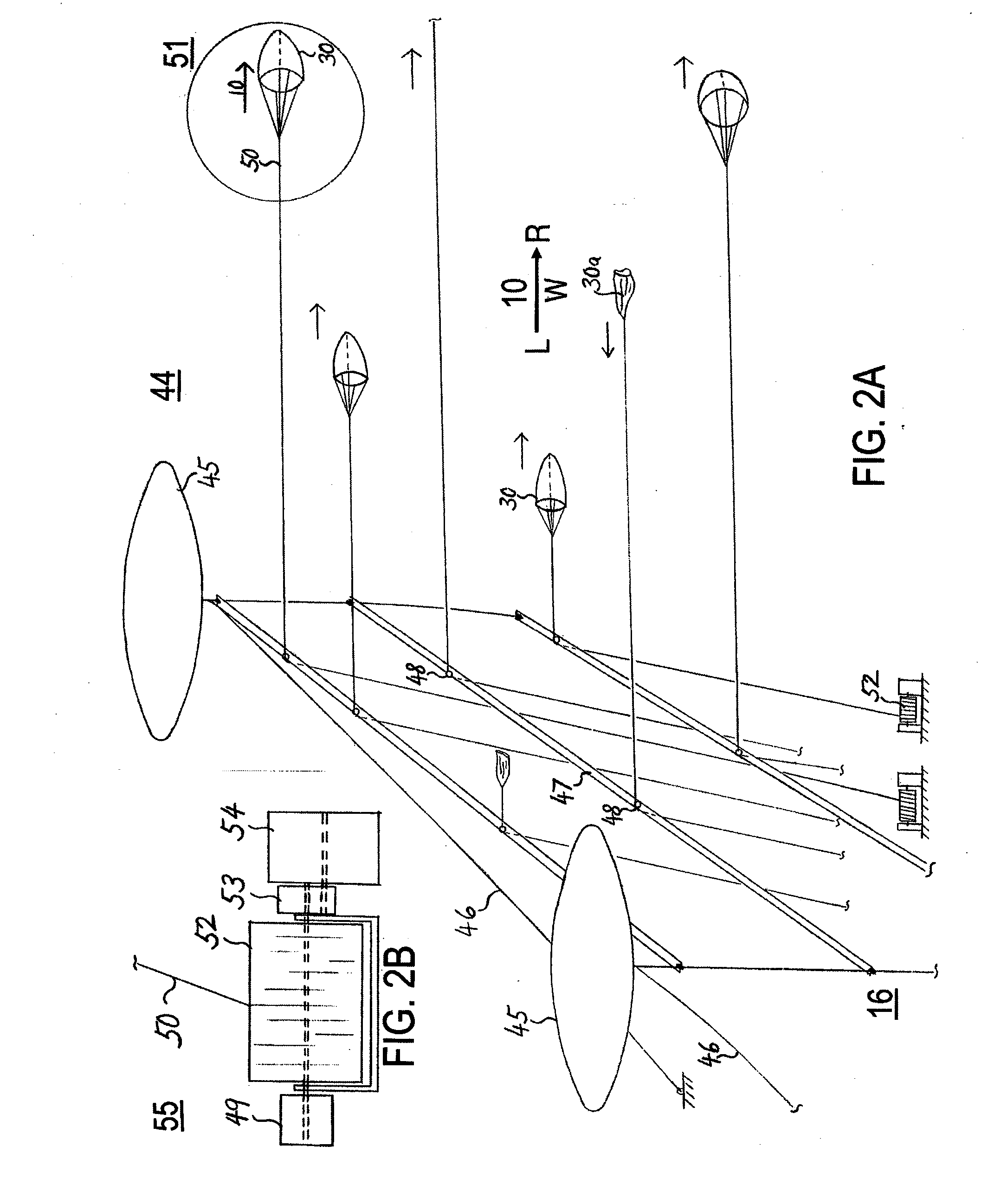
[0026]The structural configuration, concept and method of providing a plain air-bag, a windbag and / or a water-bag to trap and capture moving air current (wind) and / or water current, get carried along as it is swept away by the fluid's movement; for the generation of electricity; is herein disclosed. Using a windsock-shaped bag with a gaping “mouth” and enclosed rear-end to entrap, to capture moving wind / or water current; extracting, transforming its kinetic energy into mechanical and then electrical energy by means of a tether. In free “flight” / or flow; the windbag and / or water-bag may travel a longer distance horizontally; than rise in height / or sink in depth vertically. Due to lack of generation of aerodynamic lift, bags are incapable of actual aerial flight; in the real sense of the word “flying” as kites and planes are capable of. A windbag is only capable of actual aerial flight when integrated with airborne flying apparatus comprising: balloons / or shaped-inflatable bodies fill...


PUM


Abstract

A method of using a bagged power generation system comprising windbags and water-bags for harnessing wind and water power to produce electricity to meet the escalating energy needs of mankind. Windbags integrated with aerodynamically shaped inflatable bodies filled with lighter-than-air gas: HAV, UAV, airplanes; enabling the apparatus to attain high altitude to capture and entrap high velocity wind. Water-bags integrated with hydrodynamic shaped bodies HUV, UUV, Submarine-boats; enabling the apparatus to dive, capture and entrap swift moving tidal-currents. Attached tether-lines pulling on the rotating reel-drums and generators to produce electricity. Active control surfaces, turbo-fans, propellers provide precision control of the apparatus. A system configured to maximize fluids capture, retention and optimized extraction of its kinetic energy. An extremely scalable and environmentally friendly method, system, apparatus, equipment and techniques configured to produce renewable green energy with high productivity and efficiency.

Description

FIELD OF THE INVENTIONS[0001]This application claims the benefit of priority of SG application No. 201203067-2 filed Apr. 26, 2012, the contents of which are incorporated herein by reference for all purposes.[0002]The present invention relates to the harnessing of renewable “green” energy from the mass movement of naturally occurring fluid elements comprising wind and / or water; the capture and transformation of this kinetic energy into useful mechanical energy by means of a specialized bagged power generation system configured for producing electricity comprising of: (i) wind powered generators; (ii) water powered generators. In particular wind energy comprising: high altitude wind energy; the Jet Stream; and water energy comprising: marine currents; ocean gyres; Kuroshio; the Gulf Stream. The capture, entrapment, partial encapsulation and transformation of the fluid's kinetic energy into useful mechanical energy by means of tethers attached to the power bags; and the production of ...

Claims


Application Information

Patent Timeline
IPC IPC(8): F03D9/00F03D5/00
CPCF03D9/002F03D5/00F03B17/06Y02E10/70Y02E10/728F03D9/30F03D15/10H02K7/1853F03D9/25F03D9/008F05B2220/70F05B2240/922F05B2240/923F05B2270/18F05B2270/20Y02E10/74Y02E10/72Y02E10/30F05B2240/9176B64U10/60B64U2101/10B64U50/12B64U20/60B64U10/50Y02E10/20B64U2101/00F03D5/02H02K7/06B64C39/022B64C39/024F03D7/06
Inventor SIA, YIK HEI
Owner SIA YIK HEI
Why Eureka
Try Eureka