Method of implementing timing engineering change order

a timing engineering and change order technology, applied in the direction of cad circuit design, program control, instruments, etc., can solve the problems of difficult detection of design failures, high cost of photomasks for transistor layers, and high cost of photomasks for metal layers

Inactive Publication Date: 2013-11-07
NAT CHIAO TUNG UNIV +1
View PDF0 Cites 11 Cited by
  • Summary
  • Abstract
  • Description
  • Claims
  • Application Information

AI Technical Summary

Benefits of technology

The present invention provides a method for implementing timing engineering change order (ECO) effectively. The main technical effect is that the fixability parameter of each gate is computed using a smooth curve that takes into consideration the smoothness of the path on timing criticality. This allows for precise determination of the timing criticality of the gates.

Problems solved by technology

Since complexity in modern integrated circuit (IC) design has grown rapidly, some design failures that are hard to be detected may not be found until later stages of IC design, such as, after circuit layout, or even after chip fabrication.
The reason is that, in relevant researches, photomasks for a transistor layer is much more expensive than photomasks for a metal layer.
Therefore, how to save spare cells during the ECO runs is an important issue.
However, neither the slack nor the delay can reflect the timing criticality well, such that the timing violation may not be fixed effectively.

Method used


Image

  • Method of implementing timing engineering change order
  • Method of implementing timing engineering change order
  • Method of implementing timing engineering change order

Examples


Embodiment Construction

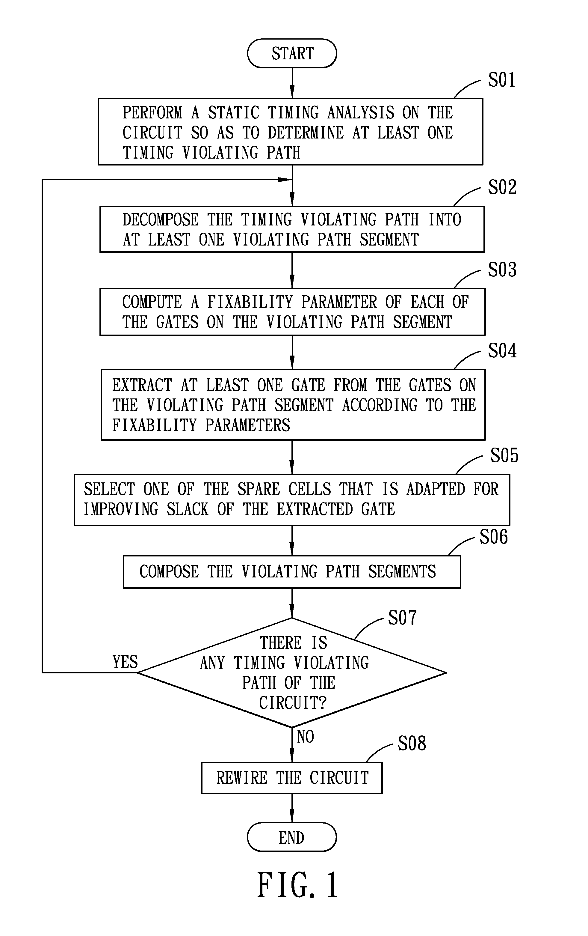
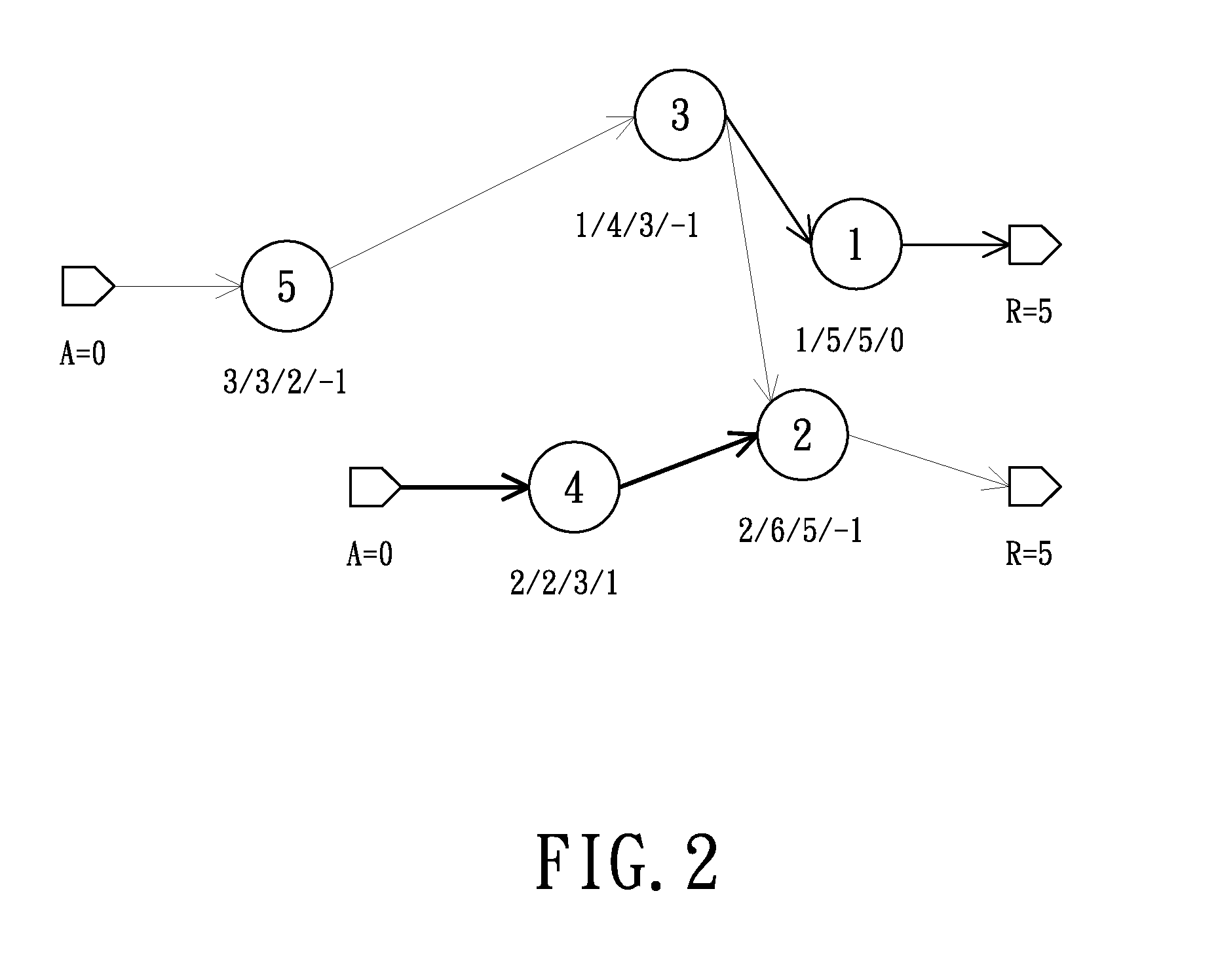
[0032]Referring to FIG. 1, a first preferred embodiment of a method of implementing timing engineering change order (ECO) according to the present invention is illustrated. The timing ECO is to be implemented in a circuit that includes a plurality of gates and that is provided with a plurality of spare cells, so as to fix timing violations of the circuit. In the following description, H=(G,E) is used to represent the circuit, wherein each node giεG represents a gate on the circuit, D(i) represents rise or fall delay of the gate gi, and each edge e(i,j)εE represents the wire between two gates gi,gjεG. Procedures for the first preferred embodiment of the method of implementing the timing ECO are illustrated hereinafter.

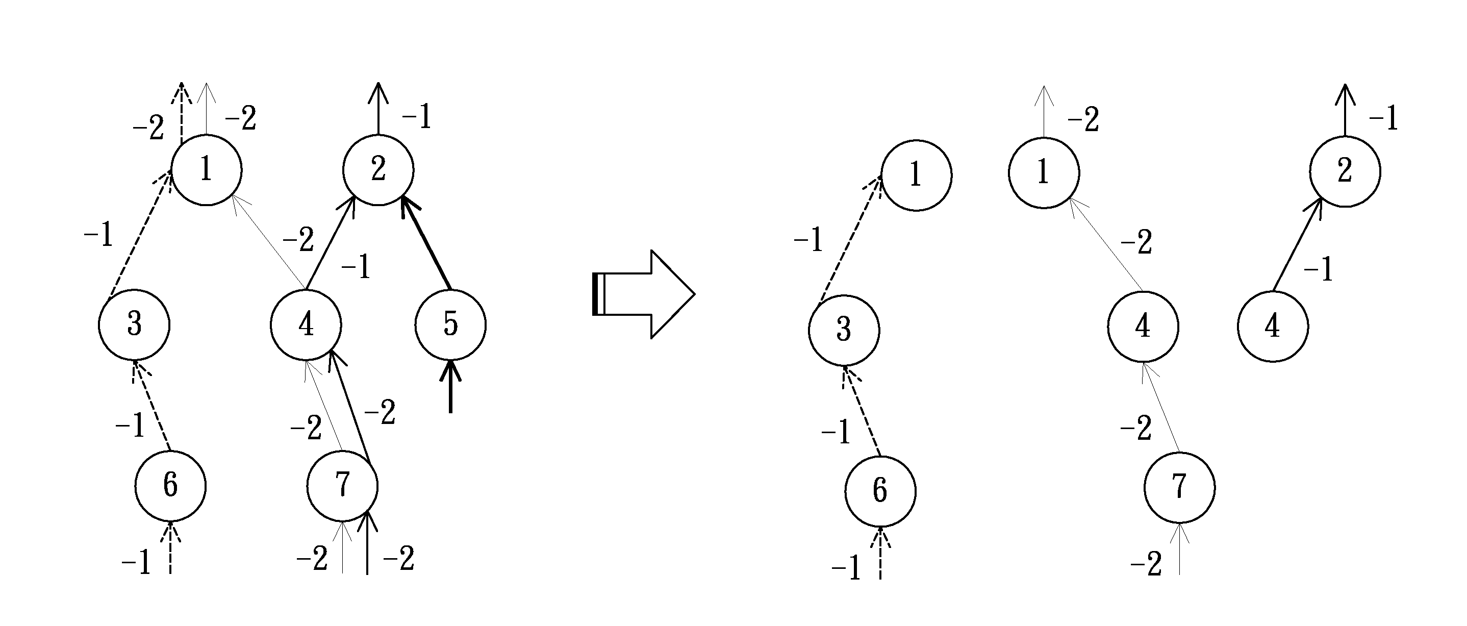
[0033]First, step S01 is to perform a static timing analysis on the circuit so as to determine at least one timing violating path of the circuit. The timing violating path includes a sequence of the gates such that from each of its gates there is a wire connecting to th...


PUM


Abstract

A method of implementing timing ECO in a circuit includes the steps of performing a static timing analysis on the circuit so as to determine at least one timing violating path of the circuit, decomposing the timing violating path into at least one violating path segment, determining a smooth curve from each timing violating path and determining a plurality of reference points along the smooth curve, computing a fixability parameter of each gate on the violating path segment, extracting at least one gate according to the fixability parameters, and selecting one spare cell and disposing the selected spare cell on the violating path segment.

Description

CROSS-REFERENCE TO RELATED APPLICATION[0001]This application claims priorities of Taiwanese Patent Application No. 101116185, filed on May 7, 2012, and No. 101128031, filed on Aug. 3, 2012.BACKGROUND OF THE INVENTION[0002]1. Field of the Invention[0003]The present invention relates to a method of implementing timing engineering change order (ECO), more particularly to a method of implementing timing ECO that takes into consideration smoothness of circuit paths.[0004]2. Description of the Related Art[0005]Since complexity in modern integrated circuit (IC) design has grown rapidly, some design failures that are hard to be detected may not be found until later stages of IC design, such as, after circuit layout, or even after chip fabrication. In order to correct the late-found design failures, it has become a trend for a current IC design house to not trace the failure back to early stages, and to adopt the metal-only engineering change order instead. The reason is that, in relevant re...

Claims


Application Information

Patent Timeline
IPC IPC(8): G06F17/50
CPCG06F30/3312G06F30/39G06F2117/06G06F2119/12G06F30/3315
Inventor CHANG, HUA-YUJIANG, HUI-RUCHANG, YAO-WEN
Owner NAT CHIAO TUNG UNIV
Why Eureka
Try Eureka