
Minimal weight composites using open structure

Active Publication Date: 2013-11-07
AUBURN UNIV
View PDF7 Cites 31 Cited by
  • Summary
  • Abstract
  • Description
  • Claims
  • Application Information

AI Technical Summary

Benefits of technology

The patent describes an invention that creates a strong and lightweight composite truss structure using a conventional braiding machine. This structure is made up of large yarns that are placed on a mandrel and then heated to cure the resin and stiffen it. The strength of the bonds between the yarns is increased by using a simple mandrel that does not require extensive machining or a complicated removal mechanism. The invention has advantages over other methods of manufacturing composite structures, including higher strength to weight ratio, faster production, and easier removal of the mandrel after curing.

Problems solved by technology

The tows are laid into rigid channels in a rigid mold (Wilson, Kipp and Ridges, U.S. Pat. No. 8,313,600: Method and system for forming composite geometric support structures, Nov. 12, 2012; http: / / www.geostrut.net / home / ) Perhaps the main difficulty of such structures is that the intersections of tapes thickens the nodes and incorporates voids as the tape transitions from the thick joint to the thinner truss member.

Method used


Image

  • Minimal weight composites using open structure
  • Minimal weight composites using open structure
  • Minimal weight composites using open structure

Examples


example 1

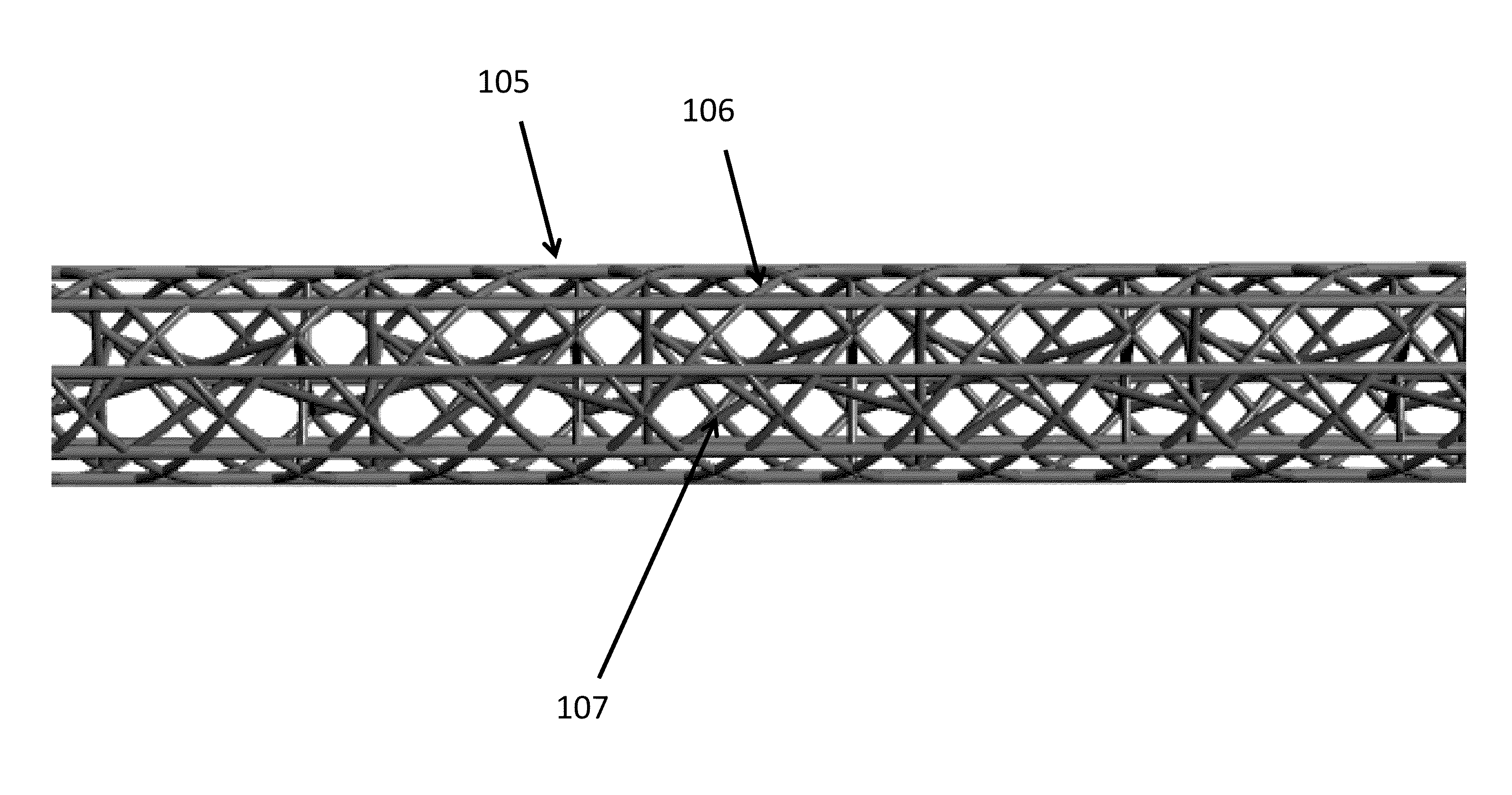
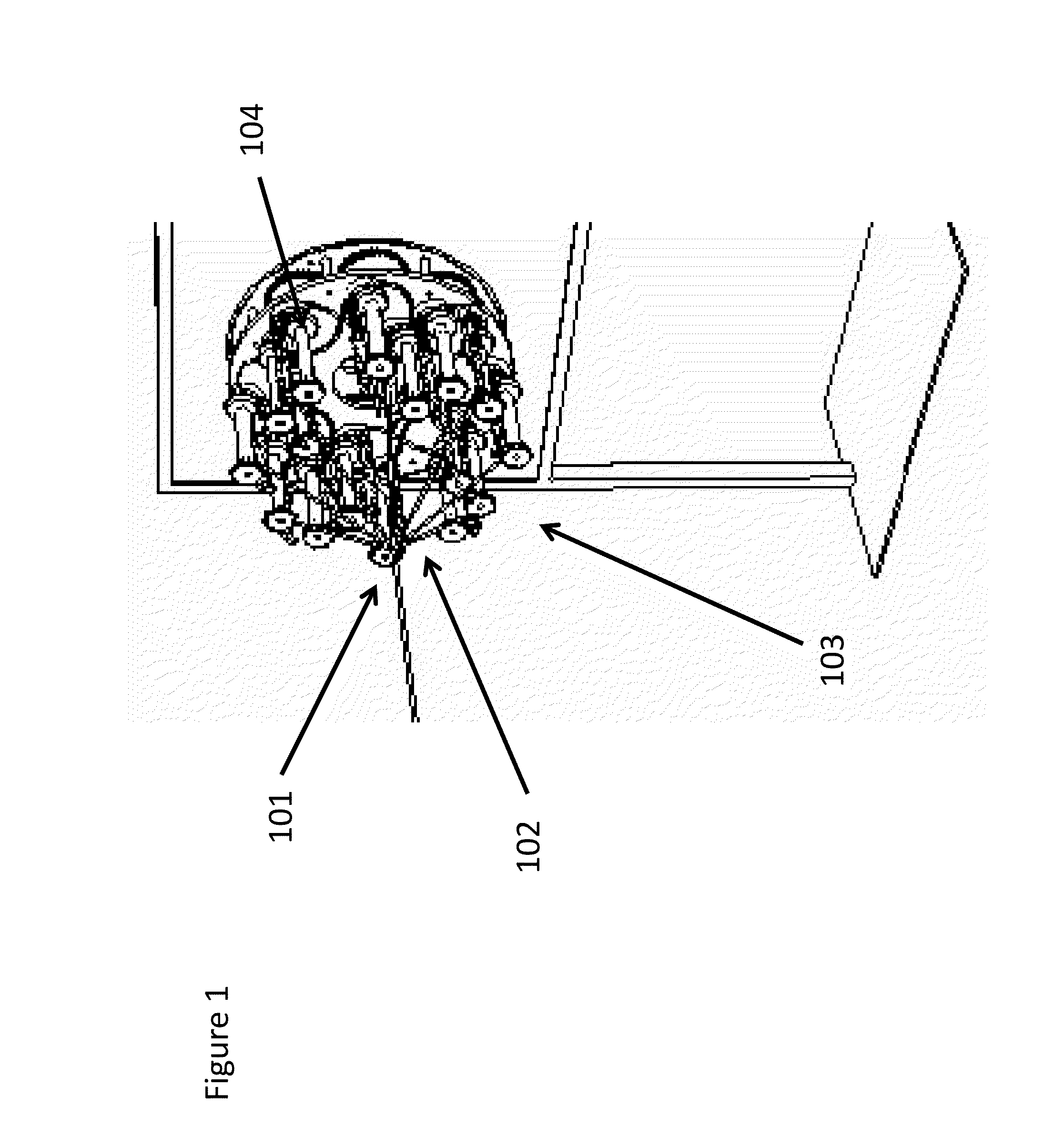
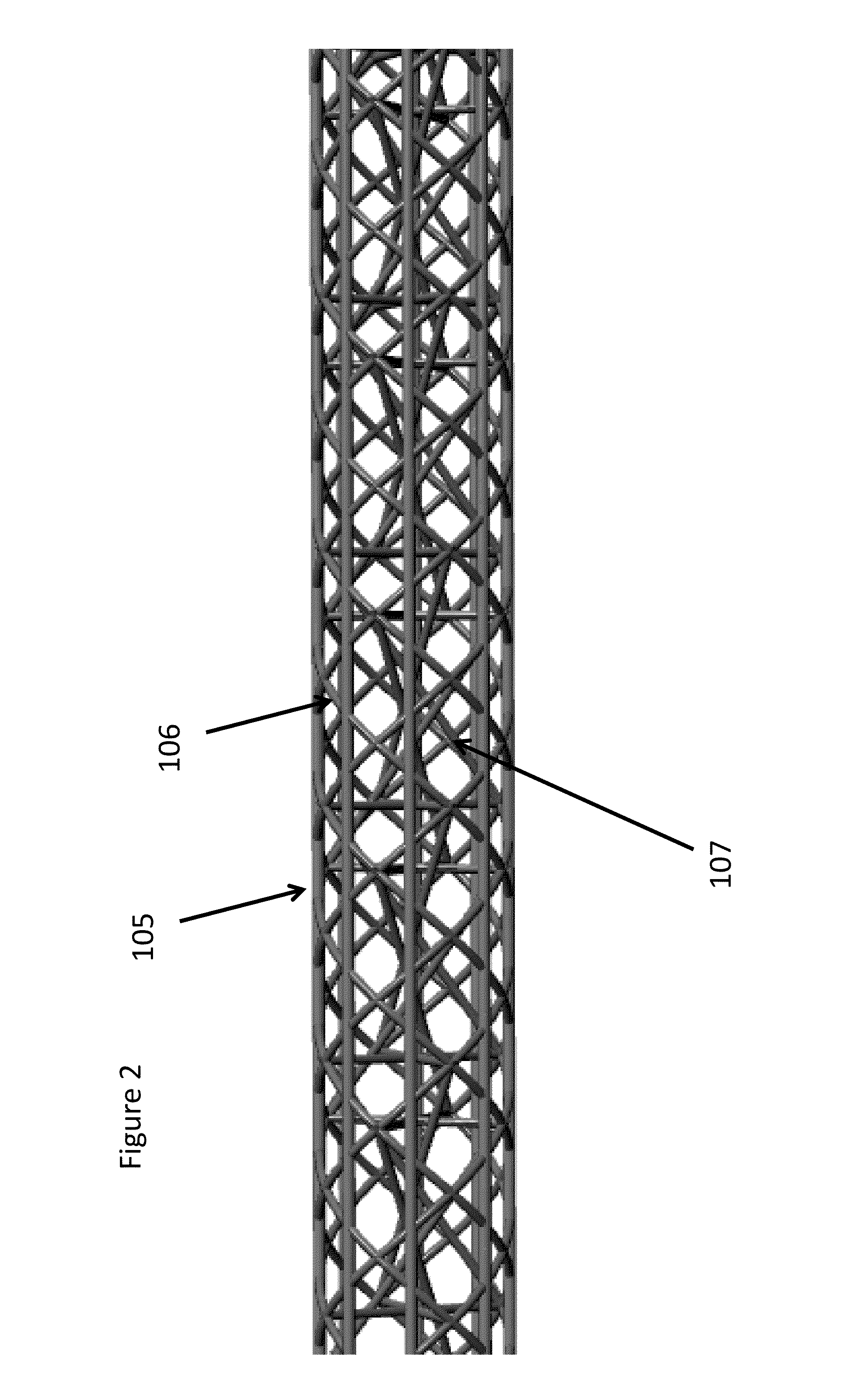
[0043]An open structured cylinder (101) was made according to the teaching of this invention, but similar in size and weight per unit length to an energy drink can and similar in size and weight to a prepreg braided sleeve constructed of carbon fiber and epoxy resin. The structure was made from a 36k assembled prepreg carbon yarn (102) (from TCR Composites) core with eight helical yarns in the jacket. The jacket yarns were 200 denier Vectran™ yarns which were braided around the 32 prepreg tow carrier jacket. The jacket consists of eight helical yarns and eight axial yarns arranged in a true triaxial configuration. The open structured composite (101) was made on a 32-carrier maypole braider (103) with four helical yarns (106) and four axial yarns (105) in the true triaxial structure (as shown in FIG. 7). In the true triaxial structure, the axial yarns (105) interlace with the helical yarns. The crossover joints in this structure (101) were reinforced with additional epoxy resin. Both...

example 2

[0044]Open structured cylinders (101) similar to that disclosed in Example 1 may be assembled into larger structures like that shown in FIG. 6. FIG. 6 is a drawing of a framework for a human powered vehicle for a student “moonbuggy” competition at NASA's Marshall Space Flight Center. The framework was constructed of cylindrical open structured trusses (101) produced in accordance with the teachings of this invention using the z direction reinforcement (107) of yarn intersection joints shown in FIGS. 2, 3, and 4.

example 3

[0045]An open truss structure was constructed using jacketed 36k carbon prepreg yarns (102)—namely, three axial (105) and eight helical (106) prepreg yarns—in a true triaxial configuration. A mandrel (108) of triangular cross section was used. Each helical prepreg yarn (106) was flanked by 2 Kevlar™ 1000 denier yarns. The structure was cured on the mandrel (108) to set the shape and then the smaller Kevlar™ flanker yarns (109) and the joints were coated with resin before curing again. The Kevlar™ yarns (109) were on either side of the cured yarns (102). The flanking yarns (109) helped to stabilize the joints. The geometry of the structure (101) is shown in FIG. 9 and in enlarged view (FIG. 10).


PUM

PropertyMeasurementUnit
Weightaaaaaaaaaa
Structureaaaaaaaaaa
Strengthaaaaaaaaaa

Abstract

Preforms for open structured (lattice) composite truss structures manufactured from large prepreg yarns on a conventional maypole braiding machine, and subsequently cured to produce fiber reinforced composites of high strength and light weight.

Description

CROSS-REFERENCE TO RELATED APPLICATION[0001]The present application claims priority to U.S. provisional application No. 61 / 624,528, filed on Apr. 16, 2012, and hereby incorporates the subject matter of the provisional application in its entirety.BACKGROUND OF THE INVENTIONField of the Invention[0002]The field of the invention is fiber reinforced composites having an open-truss of lattice structure and methods for their manufacture.Brief Description of the Related Art[0003]Until recently, structures such as frames, trusses, struts, shafts, bridges, etc. were constructed from an assemblage of standard metal elements, mass-produced and commercially available lengths and cross-sectional geometries. The geometries included plates, sheets, angles, channel sections, I-beam shapes, and hollow, circular, square and rectangular tubing (Manual of Steel Construction, 8th Edition, American Institute of Steel Construction, 1987), and are commonly made from steel or aluminum. It is well known that...

Claims


Application Information

Patent Timeline
IPC IPC(8): E04C3/28
CPCE04C3/28D04C1/02D10B2505/02Y10T29/49616Y10T428/249921Y10T428/249922Y10T428/2935B29C70/50B29K2063/00B29K2307/04D02G3/385D02G3/404D04C1/06
Inventor BROUGHTON, JR., ROY M.BRANSCOMB, DAVID J.BEALE, DAVID G.
Owner AUBURN UNIV
Learn More