Vaporization Apparatus

a technology of vaporizer and vaporizer, which is applied in the direction of indirect heat exchangers, lighting and heating apparatus, machines/engines, etc., can solve the problems of difficult heat exchanger provision, and achieve the effect of plentiful and inexpensive sources of energy

Active Publication Date: 2013-10-24
TINMAN +1
View PDF18 Cites 2 Cited by
  • Summary
  • Abstract
  • Description
  • Claims
  • Application Information

AI Technical Summary

Benefits of technology

The patent describes a method of creating a cell to produce superheated vapor. The temperature in the cell is preferably greater than 250 degrees F to avoid heat loss and ensure the vapor is produced instantly. The shape of the cell can vary widely, as long as it allows the heat to reach the interior of the cell. The distance between the surfaces of the cell can also be optimized to control heat transfer. The cell can be formed by casting the desired shape and design to match the existing structure, while still allowing for proper operation. In some cases, fins or other obstructions can be added to aid in heat transfer. Overall, the patent provides a method for efficiently producing superheated vapor in a controlled and safe manner.

Problems solved by technology

However there remains difficulty in providing a heat exchanger which extracts heat at a suitable efficiency to make this system operate effectively.

Method used


Image

  • Vaporization Apparatus
  • Vaporization Apparatus
  • Vaporization Apparatus

Examples


Embodiment Construction

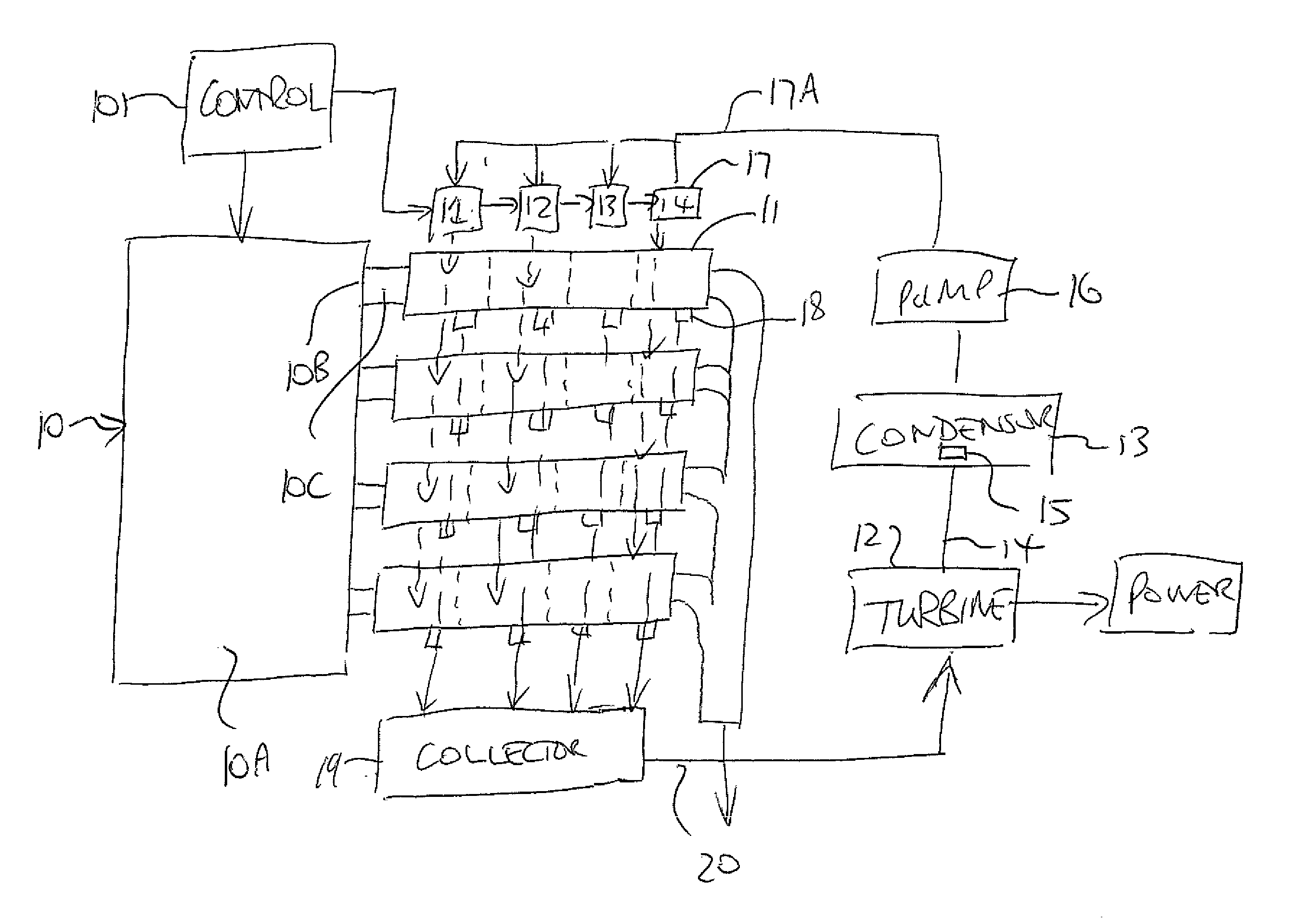
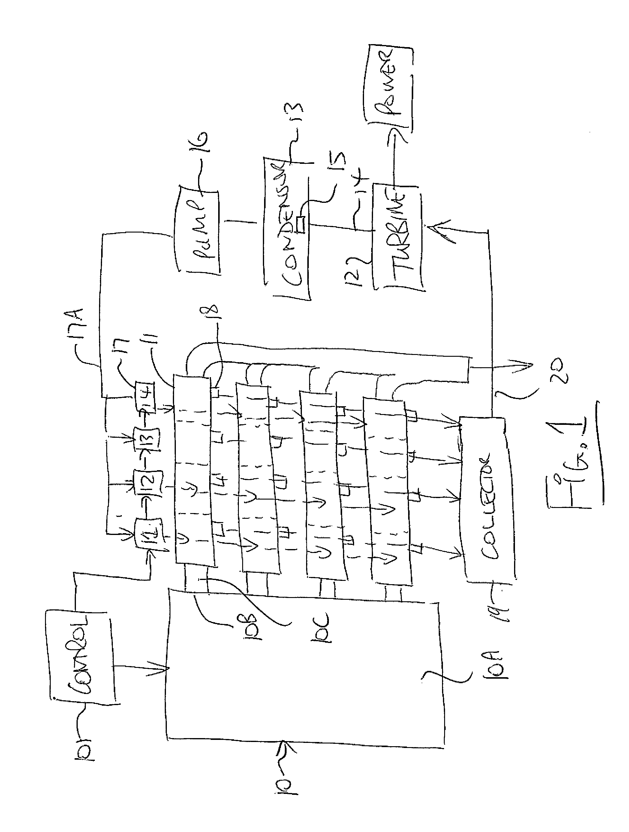
[0080]As shown in the Figures there is provided an apparatus and method for evaporating a liquid to generate a pressurized vapor. This comprises a heat source 10 in the form of an engine 10A with exhaust ports 10B feeding exhaust ducts 10C.

[0081]At each duct 10C is provided a series of vaporization cells or cores 11 developing steam for a turbine 12 driven by the vapor generated by the cell 11, a return tank 13 for the condensing vapor, a return pipe 14 to carry the steam from the outlet of the turbine which includes a diffuser 15 and a pump 16 to transfer the liquid back to the cell through injectors 17 through lines 17A.

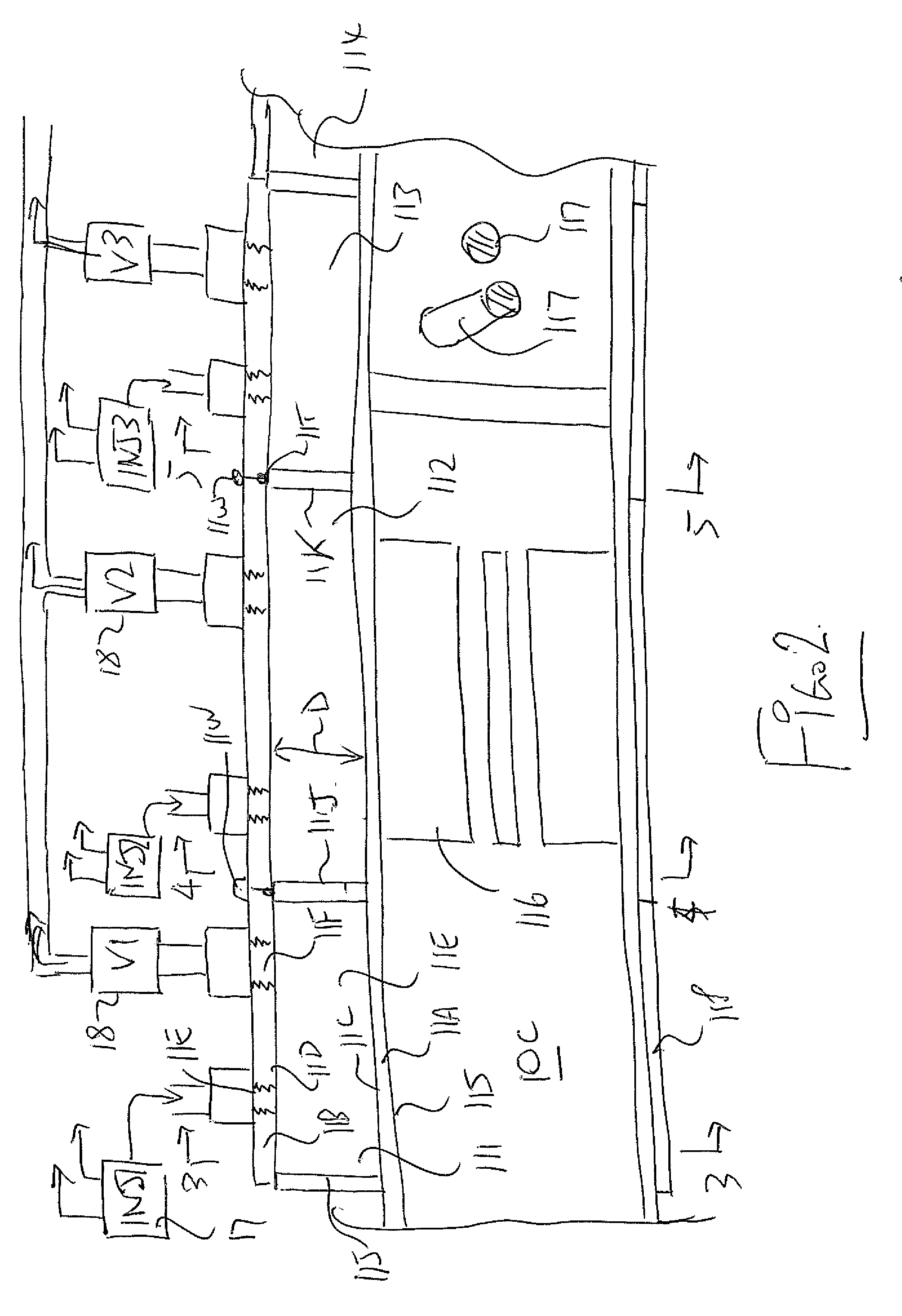
[0082]Each cell 11 includes walls defining two spaced surfaces 11C, 11D with an open chamber 11E therebetween with the surfaces located on the inside of walls 11A and 11B.

[0083]The walls 11A is in communication with a source of heat from the exhaust 10B within the duct 10C sufficient to maintain the surfaces at a temperature such that the liquid injected by injecto...


PUM


Abstract

Liquid is flash evaporated in a series of cells along and surrounding an exhaust duct to generate a pressurized vapor where at least one of the surfaces is in communication with the source of heat sufficient to maintain the surface at a temperature such that the liquid injected into the chamber is substantially instantly converted to a superheated vapor with no liquid pooling within the chamber. The liquid is introduced by controlled injectors operating at a required rate. Each of the cells is periodically discharged by a pressure controlled relief valve and the vapor from the cells combined to form a continuous stream feeding a turbine or other energy conversion device. The outer wall of the cell is offset so that it contacts the inner wall at one point around the periphery. Heat transfer ribs and bars can be provided in the duct to provide increased heat transfer where necessary.

Description

[0001]This application claims the benefit under 35 USC 119(e) of Provisional Application 61 / 546,952 filed Oct. 13, 2011, the disclosure of which is incorporated herein by reference.[0002]This invention relates to an apparatus for vaporization which can be used for example in a Rankine cycle engine to generate power from waste heat using a turbine. Such waste heat is often available from the exhaust gases of various combustion systems, such as internal combustion engines or furnaces, but other sources of heat can be used. In addition other uses of the vaporized gas, typically steam, are possibleBACKGROUND OF THE INVENTION[0003]BMW have worked in this area and have at least U.S. Pat. Nos. 6,834,503 (Freyman) and 7,520,133 (Hoetger) which show proposals in this area.[0004]However there remains difficulty in providing a heat exchanger which extracts heat at a suitable efficiency to make this system operate effectively. Typical heat exchanger use tubes often with fins to transfer heat fr...

Claims


Application Information

Patent Timeline
IPC IPC(8): F22G7/14
CPCF22G7/14F22B27/16F22B37/60F28F1/40F28D7/10B01B1/06F01N5/02F01K23/065F01K23/10F28D21/001
Inventor WEIGOLD, THEODORE S.TOUCHETTE, SHANE M.
Owner TINMAN
Why Eureka
Try Eureka