
Systems and methods of using space time block codes

a technology of space time and block codes, applied in the field of systems and methods of using space time block codes, can solve the problems of non-compliance with eirp limitations, transmitters with multiple antennas may have difficulty extending range or improving data rates

Inactive Publication Date: 2013-10-17
QUALCOMM INC
View PDF15 Cites 24 Cited by
  • Summary
  • Abstract
  • Description
  • Claims
  • Application Information

AI Technical Summary

Benefits of technology

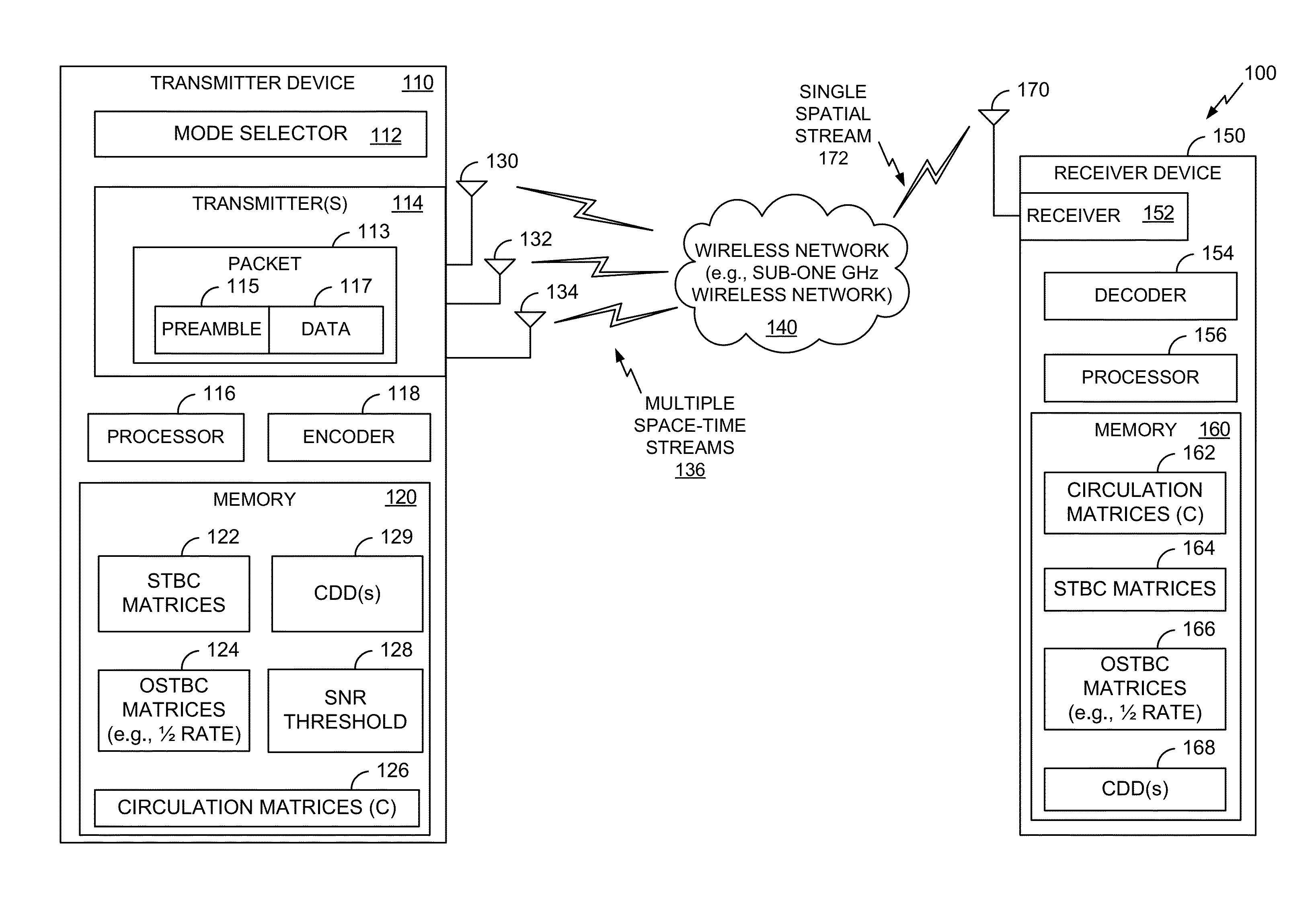
This patent describes systems and methods for using space time block codes (STBCs) for wireless communication in compliance with power requirements. The STBCs provide coding gains that do not impact EIRP levels and can be used with low-power networks like sub-1 GHz networks. They can also be used with networks operating at frequencies greater than 1 GHz. Additionally, the patent describes a method for selecting the appropriate network classification for a message based on the preamble portion of the message. Channel smoothing can also be performed on data packets transmitted using multiple space-time streams.

Problems solved by technology

In jurisdictions that have EIRP limitations imposed by regulatory bodies (e.g., the Federal Communications Commission (FCC) in the United States), beamforming may result in non-compliance with the EIRP limitations, especially when multiple transmission antennas are used.
As a result, transmitters having multiple antennas may have difficulty extending range or improving a data rate for a given range via beamforming while complying with EIRP regulations.

Method used


Image

  • Systems and methods of using space time block codes
  • Systems and methods of using space time block codes
  • Systems and methods of using space time block codes

Examples


first embodiment

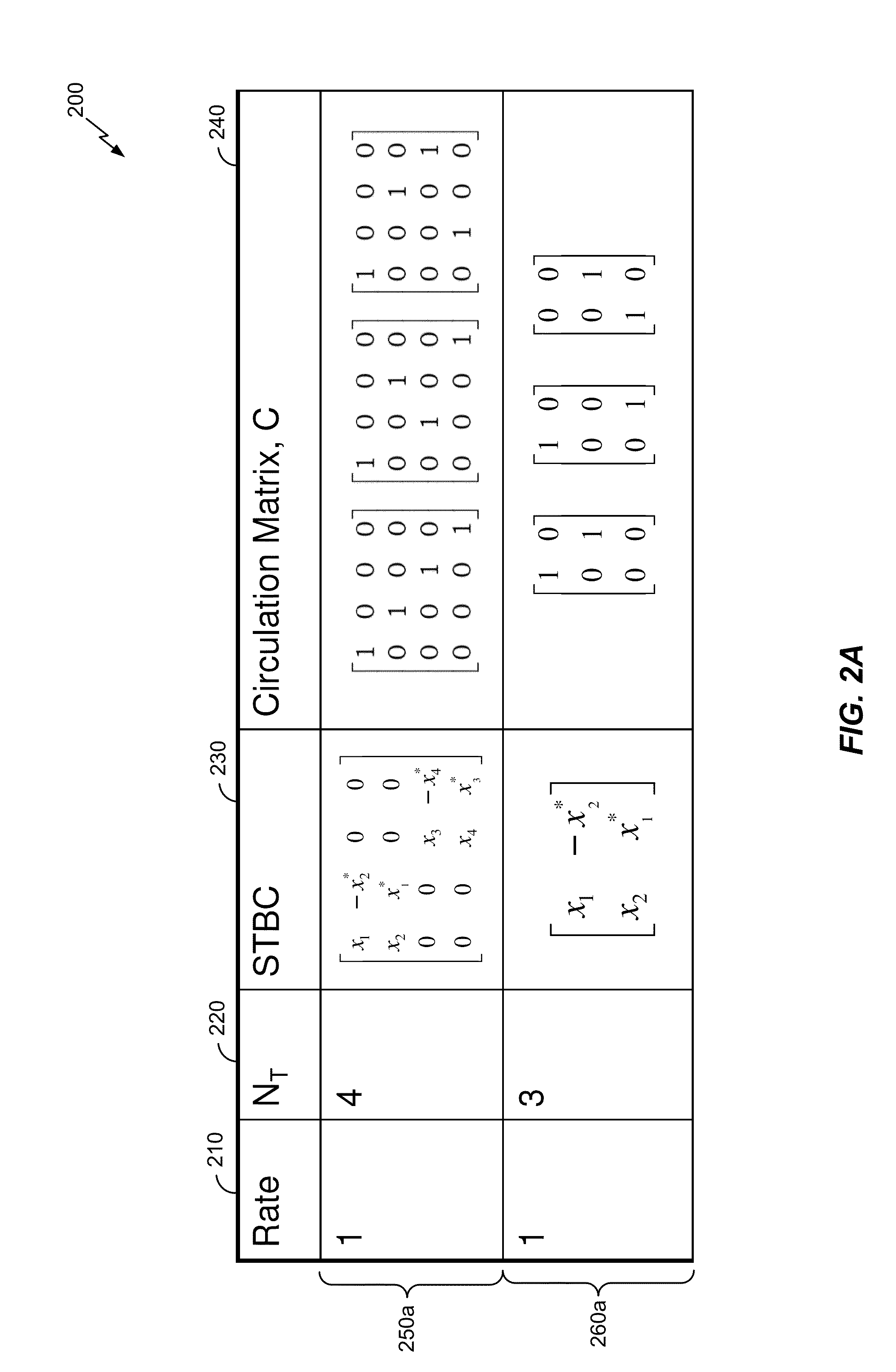
[0082]Using the CDD scheme, the same digital data may be carried by each transmit antenna of multiple transmit antennas, but with different cyclic delays (e.g., different cyclic shift delays (CSDs)). Such a varying CDD can be achieved via application of a cyclic shift matrix C (e.g., a spatial expansion matrix) that may include entries with a phase varying linearly (e.g., slowly) across frequency. For example, such a cyclic shift matrix (e.g., a base CDD matrix) may include:

C=[10p30010p4p10100p201].

[0083]where pi=ej2ΠkΔFTCSi, where k is a sub-carrier index, and where ΔF is a sub-carrier spacing for an orthogonal-frequency division multiplexing (OFDM) transmission. In the first embodiment, TCS represents a cyclic shift delay (CSD) on a space-time stream i when contributing on an antenna other than antenna i.

second embodiment

[0084]such a cyclic shift matrix C may include:

C=[10000p20000p30000p4][1010010110100101],

[0085]where pi=ej2ΠkΔFTCSi, where k is a sub-carrier index, and where ΔF is a sub-carrier spacing for an orthogonal-frequency division multiplexing (OFDM) transmission. In the second embodiment Tis represents a cyclic shift delay (CSD) on antenna i.

[0086]In a particular embodiment, a cyclic shift matrix includes at least one element that is based on a pseudo-random pattern having a frequency periodicity that is selected based at least in part on a frequency width of an EIRP measurement frequency window. For example, a value of TCS may be selected such that a resulting periodicity of a pattern of pi is greater than an EIRP measurement bandwidth used by a regulatory body (e.g., the FCC). For example, the EIRP measurement frequency window may be associated with an EIRP value of a wireless device. In a particular embodiment, the EIRP value of the wireless device is less than a threshold value, such ...


PUM


Abstract

In a particular embodiment, a method includes applying a first stream to antenna mapping scheme to a preamble portion of a packet. The method further includes applying a second stream to antenna mapping scheme to a data portion of the packet. The second stream to antenna mapping scheme is applied to the data portion of the packet but not to the preamble portion of the packet. The second stream to antenna mapping scheme includes a circulation scheme or a cyclic delay diversity (CDD) scheme.

Description

I. CLAIM OF PRIORITY[0001]This application claims priority from U.S. Provisional Patent Application No. 61 / 625,045, filed Apr. 16, 2012, entitled “SYSTEMS AND METHODS OF USING SPACE TIME BLOCK CODES” and U.S. Provisional Patent Application No. 61 / 668,416, filed Jul. 5, 2012, entitled “SYSTEMS AND METHODS OF USING SPACE TIME BLOCK CODES,” the contents of which are incorporated by reference in their entirety.II. FIELD[0002]The present disclosure is generally related to systems and methods of using space time block codes (STBCs).III. DESCRIPTION OF RELATED ART[0003]Advances in technology have resulted in smaller and more powerful computing devices. For example, there currently exist a variety of portable personal computing devices, including wireless computing devices, such as portable wireless telephones, personal digital assistants (PDAs), and paging devices that are small, lightweight, and easily carried by users. More specifically, portable wireless telephones, such as cellular tel...

Claims


Application Information

Patent Timeline
IPC IPC(8): H04B7/08
CPCH04B7/0891H04B7/0669H04B7/0671H04B7/0689H04L1/0011H04L1/0668
Inventor VERMANI, SAMEERVAN NEE, RICHARDVAN ZELST, ALBERTJONES, VINCENT KNOWLESSAMPATH, HEMANTH
Owner QUALCOMM INC
Learn More