
Embedded optics in modular assemblies

a technology of embedded optics and modular assemblies, applied in the field of modular assembly construction, can solve the problems of limiting the flow of adhesive out of the assembly or otherwise flowing, affecting the quality of the product, so as to achieve the effect of reducing costs

Active Publication Date: 2013-10-17
TESLA INC
View PDF11 Cites 16 Cited by
  • Summary
  • Abstract
  • Description
  • Claims
  • Application Information

AI Technical Summary

Benefits of technology

This patent describes methods and systems for reducing expenses associated with using adhesives for assembling modularized components, particularly battery modules used in electric vehicles. The methods involves using selectively curable adhesives like UV reactive adhesives, which can provide a stiff, robust, and electrically insulating mechanical connection to the battery module fixture. The high-wettability adhesive allows for efficient filling of the bonding wells without overfilling while curing the adhesive with UV radiation. The patent also discusses different implementation of the methods using one-part or two-part adhesives with or without sealing formulations. The technical effects of this patent include reducing costs associated with adhesive use, improving mechanical integration, and promoting even distribution of the adhesive for efficient bonding.

Problems solved by technology

This limits adhesive from exiting the assembly or otherwise flowing to undesirable locations during manufacture.
For example, depending upon details of the curing modality and the specifics of the module assembly, there are instances where the curing modality is distorted and does not always produce an optimal cure profile.
Distortions in the curing modality produce less than an optimum curing pattern for the adhesive, which can lead to leakage and waste.
Further, application of adhesive in undesired areas necessitates additional efforts at remediation.

Method used


Image

  • Embedded optics in modular assemblies
  • Embedded optics in modular assemblies
  • Embedded optics in modular assemblies

Examples


Embodiment Construction

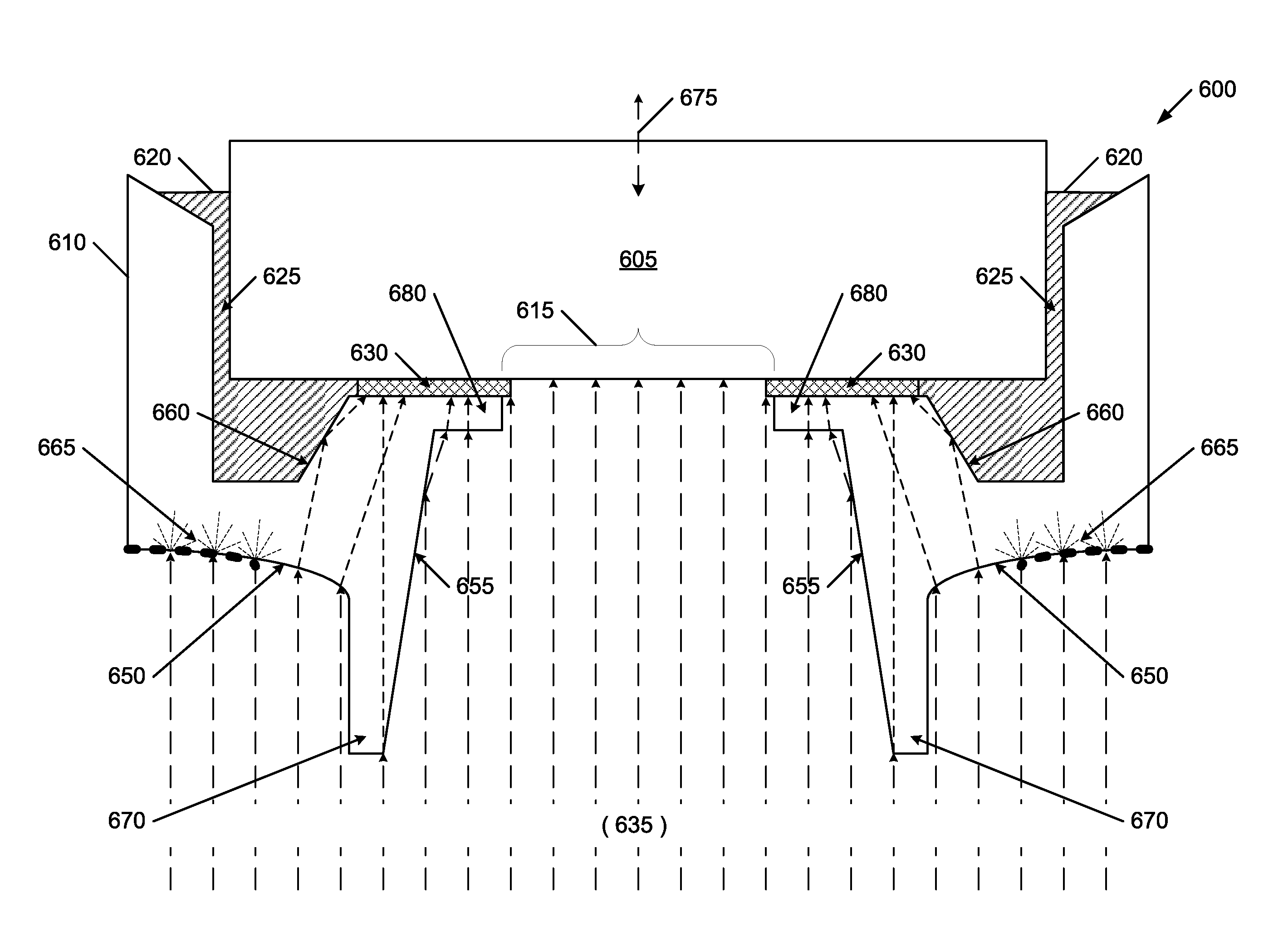
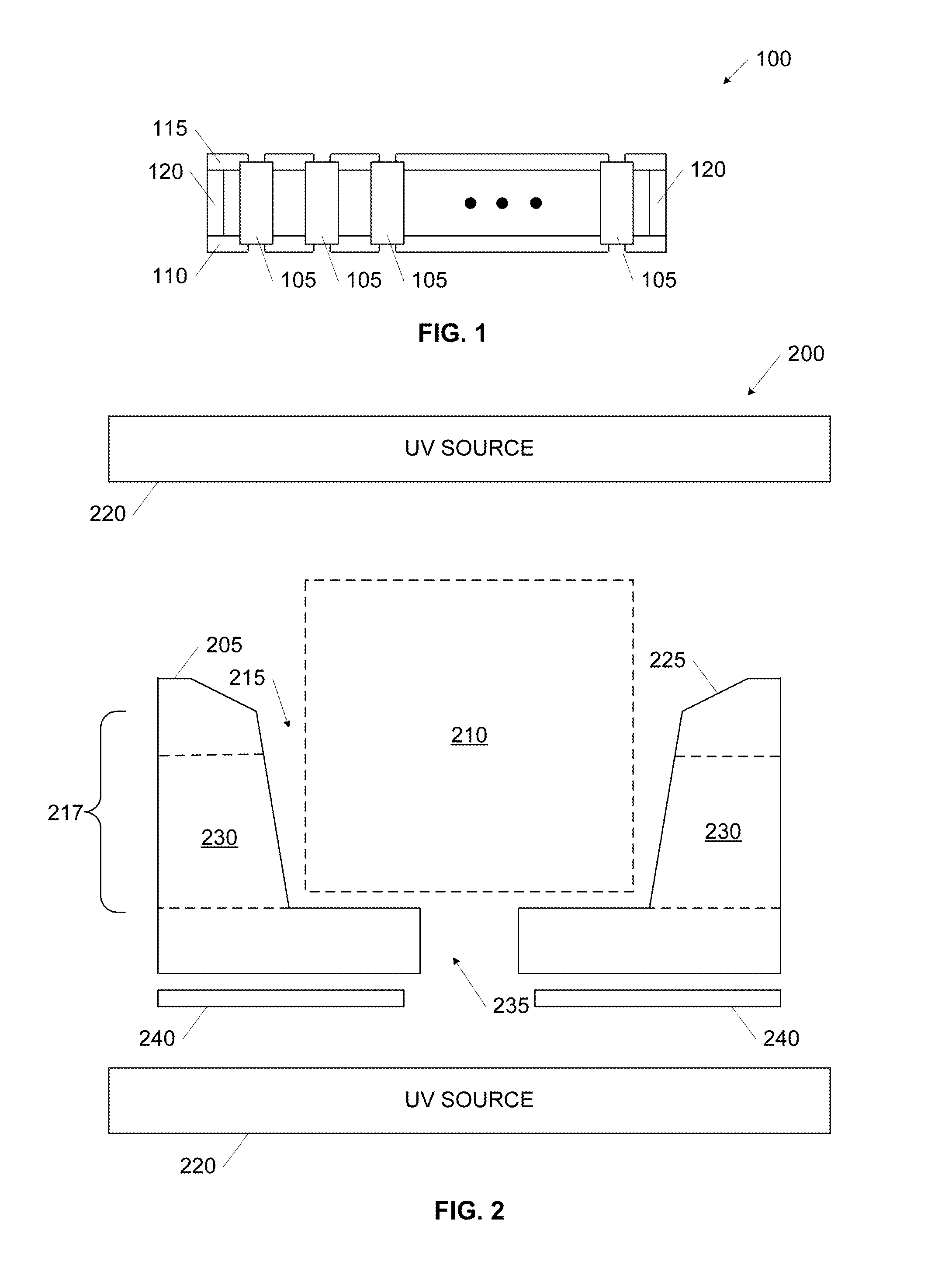
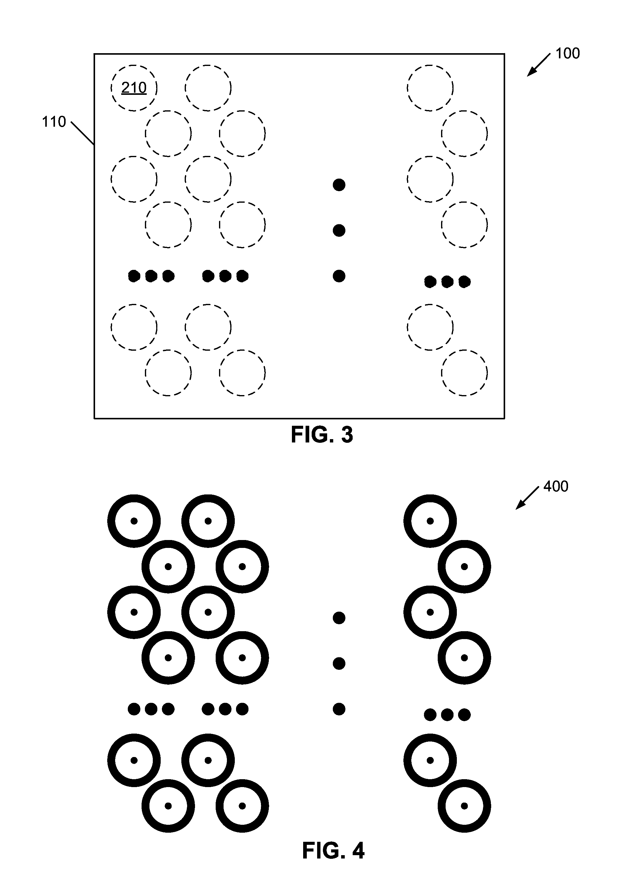
[0022]Embodiments of the present invention provide methods and systems for decreasing costs (expense, mass, and / or cure time) associated with use of adhesives when assembling modularized components by enabling use of high-wettability adhesives. The following description is presented to enable one of ordinary skill in the art to make and use the invention and is provided in the context of a patent application and its requirements. In the following text, the terms “battery”, “cell”, and “battery cell” may be used interchangeably and may refer to any of a variety of different rechargeable cell chemistries and configurations including, but not limited to, lithium ion (e.g., lithium iron phosphate, lithium cobalt oxide, other lithium metal oxides, etc.), lithium ion polymer, nickel metal hydride, nickel cadmium, nickel hydrogen, nickel zinc, silver zinc, or other battery type / configuration. Various modifications to the preferred embodiment and the generic principles and features describe...


PUM


Abstract

An enhanced multiobject potting fixture for exposure to a curing modality that sets an adhesive includes a fixture housing supporting a plurality of objects, the fixture housing having a wall defining a plurality of bonding wells with each the bonding well receiving a first portion of one of the objects, each the bonding well including an aperture in the wall proximate the first portion wherein each bonding well includes a target zone for selective cure of the adhesive to inhibit the adhesive from exiting the aperture; and a fixture enhancement structure integrated into the wall concentrating the curing modality in each the target zone.

Description

CROSS REFERENCE TO RELATED APPLICATIONS[0001]This application is related to U.S. Pat. No. 8,057,630 entitled “SELECTIVE CURE OF ADHESIVE IN MODULAR ASSEMBLIES” issued Nov. 15, 2011 and U.S. application Ser. No. 13 / 244,665 entitled “SELECTIVE CURE OF ADHESIVE IN MODULAR ASSEMBLIES” filed Sep. 25, 2011, the contents of these references expressly incorporated in their entireties for all purposes by reference thereto.BACKGROUND OF THE INVENTION[0002]The present invention relates generally to module construction for assemblies having several-to-many elements, and more specifically, but not exclusively, to optical systems and methods for tuning cure profiles of selectively curable adhesives, most particularly for battery module assembly construction using ultraviolet radiation.[0003]As noted in the incorporated references, it is common to produce module assemblies having elements secured together into an integrated monolithic structure. One method for securing the elements together uses a...

Claims


Application Information

Patent Timeline
IPC IPC(8): B29C35/08B29C45/14H01M50/213H01M50/227H01M50/264
CPCB29C2035/0827B29C35/0894Y02E60/10H01M50/213H01M50/264H01M50/227B32B3/26H01M2220/20B29C65/4845B29C66/301B29C66/5324B29C66/73343B29L2031/3468
Inventor HACHTMANN, BRIAN DEANRIEGEL, MARKHEGEMAN, DAVID ELIASBISHOP, WILLIAM CHRISTOPHERBEECHER, WILLIAM VUCICH
Owner TESLA INC
Learn More