On-chip 4d lightfield microscope

a microscope and light field technology, applied in the field of on-chip lensless microscope systems, to achieve the effect of greater automation of microscope operation

Active Publication Date: 2013-08-29
CSIR
View PDF19 Cites 32 Cited by
  • Summary
  • Abstract
  • Description
  • Claims
  • Application Information

AI Technical Summary

Benefits of technology

The present invention improves the resolution of optofluidics by increasing the sampling rate and using standard bulk CMOS technology for low-cost label-free bio-detection. It also increases sensitivity and specificity by changing the investigation point of view and depth of file. Most bio-samples are clustered, and the invention makes it easier to count and distinguish cells by making the point-of-view and depth of filed adjustable. The invention also utilizes the 4D lightfield to generate 3D images through computational photography. It records and controls the lightfield captured by an optofluidic microscope, allowing for manipulation of viewpoint and focus after the snapshot has been taken. The ability to focus on specific parts of the specimen increases sensitivity and specificity. Additionally, the invention can capture focused stacks at different depths and utilize them for volume rendering. The method also includes recording and controlling the lightfield, employing computer vision algorithms, and utilizing adaptive depth of field and spatial views.

Problems solved by technology

As they stand, these devices are not yet appropriate for use in the extreme resource-poor settings of developing countries; nevertheless, these advances place the field of LOC research in a prime position to tackle the profound issue of global health, where the challenges in device designs are arguably the most demanding, and the need for new health technologies the greatest.Yang et al., U.S. Pat. No. 7,751,048, for an Optofluidic Microscope Device, discloses a device having light transmissive regions and an optical detector that is used to image an object flowing through a fluid channel.Ciu et al., U.S. Pat. No. 7,768,654, for an On-Chip Phase Microscope / Beam Profiler Based On Differential Interference Contrast And / Or Surface Plasmon Assisted Interference, discloses a DIC microscope and / or light field profiler based on Young's interference.Yang et al., U.S. Pat. No. 7751048, for an Optofluidic Microscope Device Featuring A Body Comprising A Fluid Channel And Having Light Transmissive Regions, discloses a device that includes a fluid channel having a surface and an object such as a bacterium or virus flowing through the fluid channel while light imaging elements in the bottom of the fluid channel are used to image the object.Fletcher et al., PCT Publication Number WO2009 / 088930, for a High Numerical Aperture Telemicroscopy Apparatus, discloses an imaging system consisting of a cell-phone with a camera that is used for disease diagnosis, symptom analysis and post-procedure monitoring.Raskar et al., U.S. Pat. No. 7,792,423, for a 4D Light Field Camera, discloses a camera that acquires a 4D light field of a scene by modulating the 4D light field before it is sensed.

Method used


Image

  • On-chip 4d lightfield microscope
  • On-chip 4d lightfield microscope
  • On-chip 4d lightfield microscope

Examples


Embodiment Construction

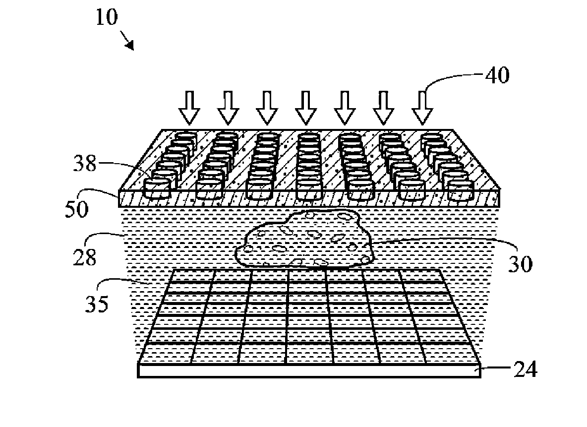
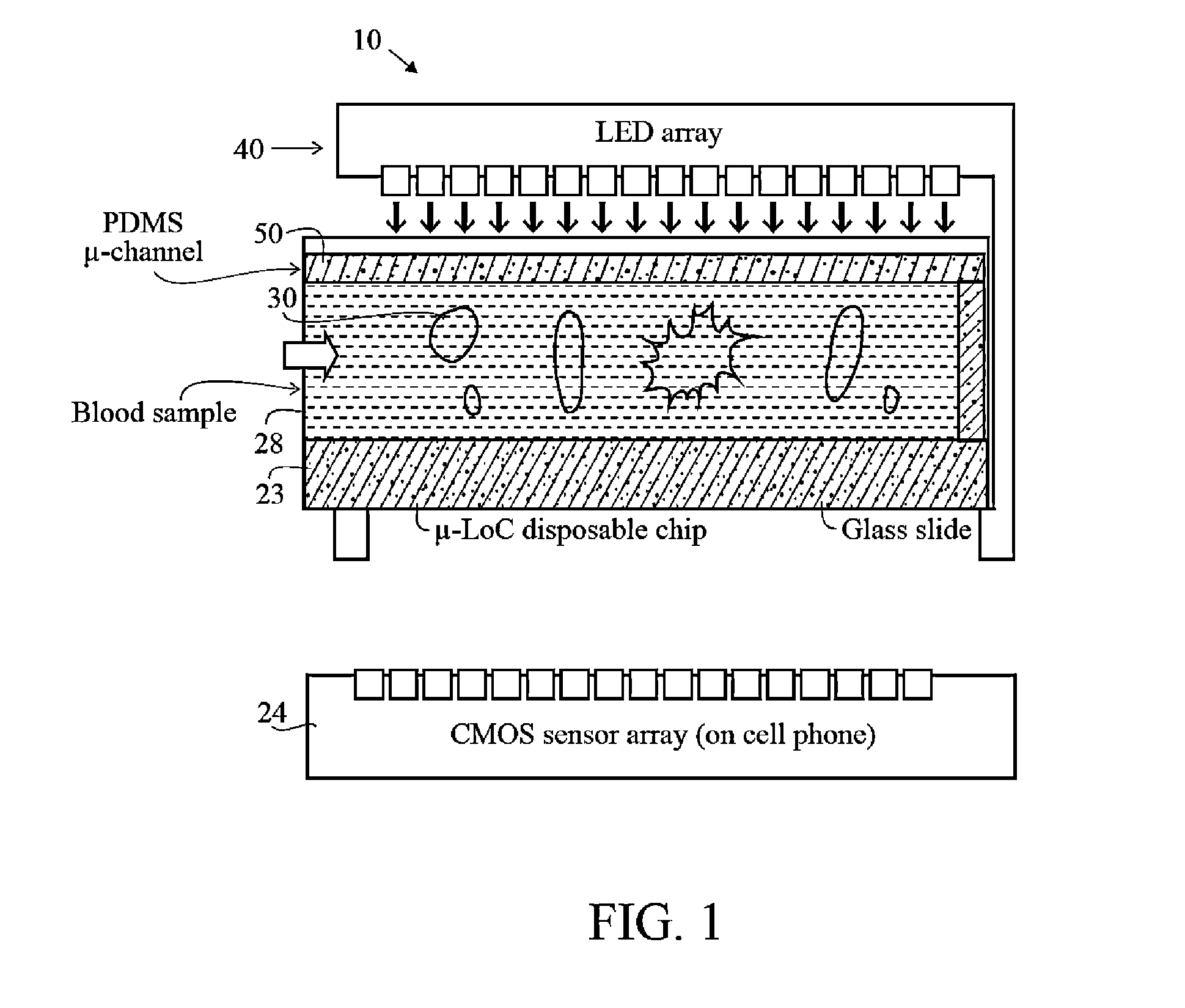
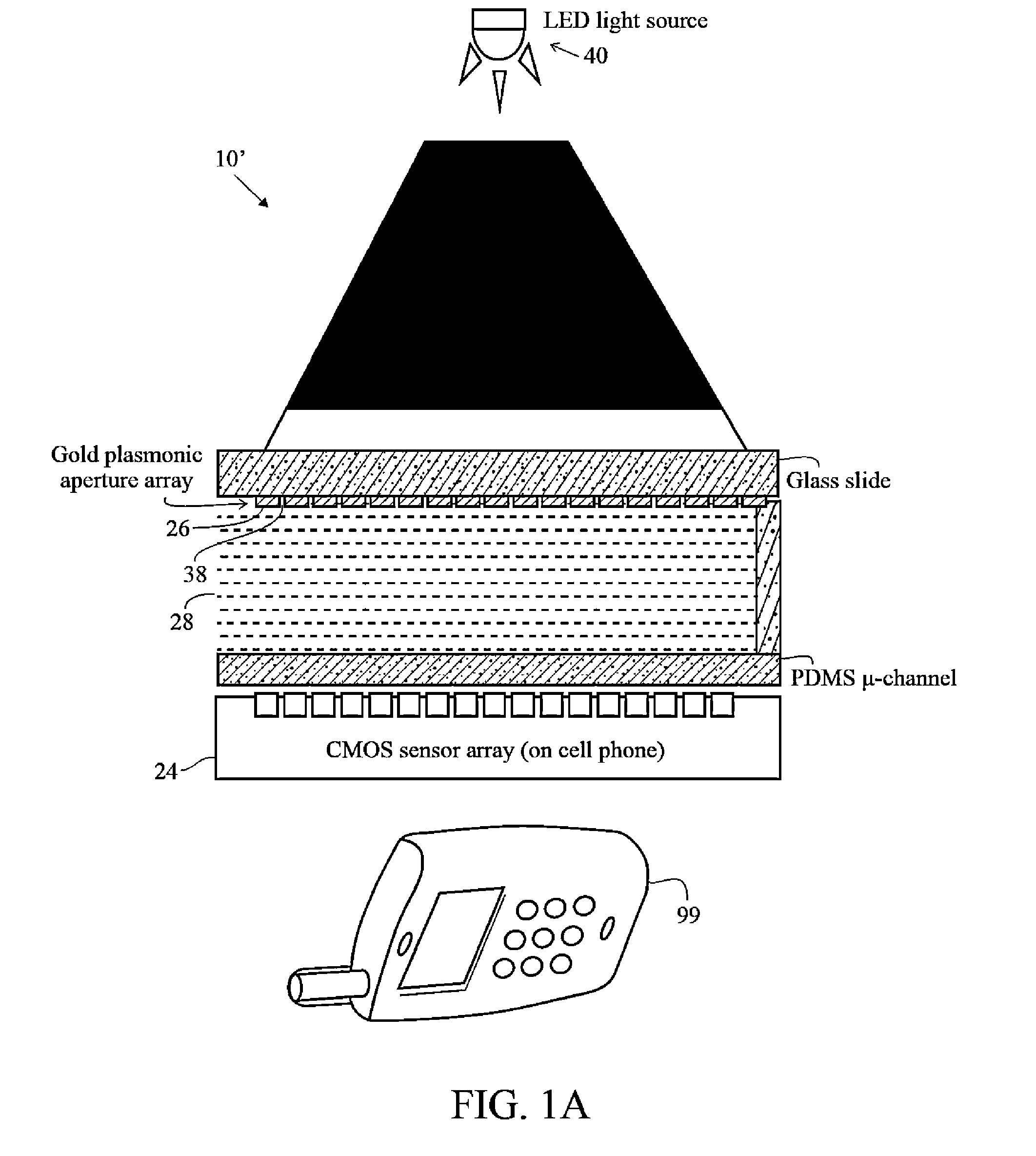
[0042]The present invention extends on-chip lensless microscope systems, including optofluidic microscope (OFMs) and holographic imaging microscopes to incorporate computational photography principles. This provides a three-dimensional imaging system for improved visualization and increased throughput. Optofluidic microscope and holographic imaging microscopes are described in greater detail in: 1) X. Q. Cui, L. M. Lee, X. Heng, W. W. Zhong, P. W. Sternberg, D. Psaltis, and C. H. Yang, Proc. Natl. Acad. Sci. U.S.A., 2008, 105, 10670-10675, 2) X. Heng, D. Erickson, L. R. Baugh, Z. Yagoob, P. W. Sternberg, D. Psaltis and C. H. Yang, Lab Chip, 2006, 6, 1274-1276, and 3) Seo, S., Su, T.-W., Tseng, D. K., Erlinger, A. and Ozcan, A., Lab Chip, 2009, 9, 777-787, all three of which are hereby incorporated by reference in its entirety.

[0043]The OFM method preferably utilizes simplified microfluidic flow to transport biological samples across a linear array of small apertures on a metal coate...


PUM


Abstract

The present invention extends on-chip lensless microscope systems (10), including optofluidic microscope (OFMs) and holographic imaging microscopes to incorporate computational photography principles. A LF-OFM system 10 includes at least one plasmonic lens (50) with apertures (38), at least one microfluidic channel (28), and an image sensor array (24). The system (10) is capable of generating an image through computational photography.

Description

TECHNICAL FIELD[0001]The present invention generally relates to on-chip lensless microscope systems, including optofluidic microscope and holographic imaging microscopes.BACKGROUND ART[0002]Affordable diagnostics is emerging as a major need for the 21st century to ensure personal diagnostics and point of care healthcare, which is critical for both the developing countries (from the standpoint of low cost) and developed countries (considering the overwhelmed medical infrastructure due to the large aging population). With the help of modern engineering technologies, measurements and biomarker detections, critical information can be extracted and the signature of chemical marker of the disease can be observed in single drop of human fluid (blood, interstitial fluid, urine, or saliva). Since the biological samples are normally limited and concentrations of molecules of interest or proteins in samples are mostly in pmol / L range, a highly sensitive, specific, and accurate detector is esse...

Claims


Application Information

Patent Timeline
IPC IPC(8): G02B21/36H01L27/146A61B5/00G03H1/00
CPCG02B21/0004G03H1/0443A61B5/0033H01L27/1462G02B21/367G03H1/0005G02B21/365G02B21/0008
Inventor VAN ROOYEN, PIETERHUGO, SUZANNE
Owner CSIR
Why Eureka
Try Eureka