Computer system

a computer system and computer technology, applied in the field of virtual machine systems, can solve the problems of increasing power consumption, large processing time cost and time cost of blocking methods, and achieve the effect of reducing power consumption

Active Publication Date: 2013-08-22
HITACHI LTD
View PDF2 Cites 2 Cited by
  • Summary
  • Abstract
  • Description
  • Claims
  • Application Information

AI Technical Summary

Benefits of technology

The technical effect of this patent is to reduce the time it takes for a virtual processor to switch from a stop state to a normal operating state, so that programs can be executed more quickly on those processors. This is accomplished by using a method called a busy wait, which allows the virtual processor to wait for an exit from a virtual halt state and rapidly resume execution of a program. This method guarantees that the physical processor utilization ratio and power consumption are minimized to the background-art method.

Problems solved by technology

Power consumption has increased as processor performance has increased with the advance of processor multiplexing and increase in cache capacity.
The blocking method is however large in processing time cost.
The processing time cost of the context switch of the blocking method affects latency of halt exit of the virtual processor.
The value of the latency causes a performance issue for some work loads.
In the blocking method, latency of virtual halt exit of the virtual processor is so large that the value of the latency causes a performance issue when the virtual processor is halted frequently.
However in this method, context saving of the virtual processor is only deferred.
Accordingly, this method cannot be applied to a virtual machine system in which a large number of virtual processors operate, because there is a high possibility of failure of skipping context switching and the physical processor utilization ratio may became low.
However for quite a few work loads the processor is halted frequently but the virtual processor utilization ratio may be low.
In this case, it is uncertain from the processor utilization ratio that it is necessary to reduce the processing time required for switching the virtual processor from a virtual halt state to a virtual normal operating state.

Method used


Image

  • Computer system
  • Computer system
  • Computer system

Examples


Embodiment Construction

[0038]An embodiment of the invention will be described in detail with reference to the drawings.

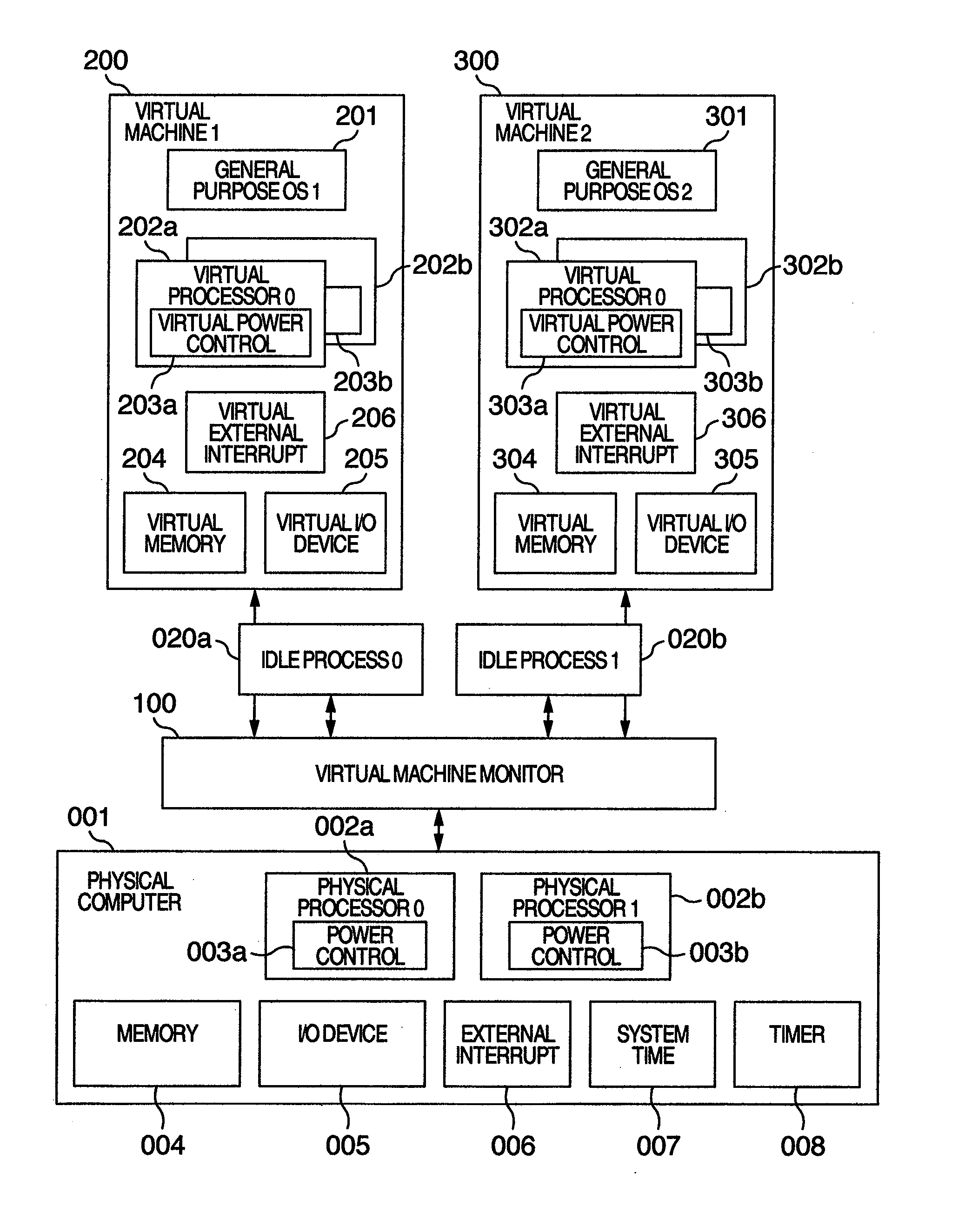
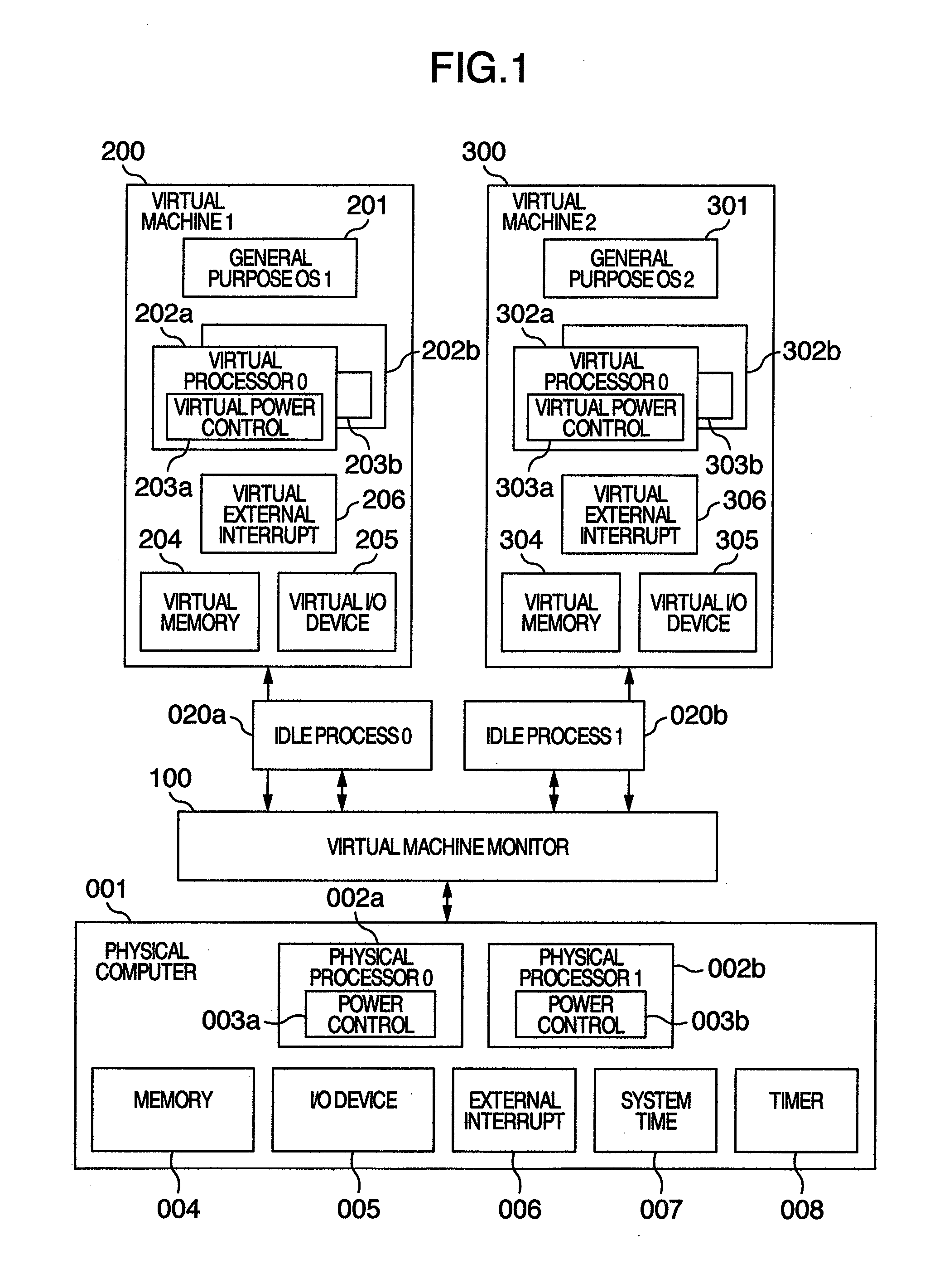
[0039]FIG. 1 is a configuration diagram showing the outline of a virtual machine system according to the invention. The virtual machine system is roughly classified into a physical computer 001, a virtual machine monitor 100 and first and second virtual machines 200 and 300.

[0040]The physical computer includes a physical processor 0 (002a), a physical processor 1 (002b), a memory 004, at least one I / O device 005, an external interrupt mechanism 006, a system time 007, and a timer 008.

[0041]The physical processors 0 (002a) and 1 (002b) are of such a type that a general purpose operating system can operate. The physical processors 0 (002a) and 1 (002b) include power control functions 003a and 003b respectively. Although FIG. 1 shows the case where the number of physical processors is 2, the number of physical processors in the invention is not limited. The invention can be applied to a phys...


PUM


Abstract

In a computer system according to the background art, when a request to halt a virtual processor was detected, the virtual processor was blocked. In the blocking method, latency of virtual halt exit of the virtual processor was so long that a problem of performance was caused. A virtual machine monitor selects either of a busy wait method for making repeatedly examination until the virtual halt state exits while the virtual processor stays on the physical processor and a blocking method for stopping execution of the virtual processor and scheduling other virtual processors on the physical processor while yielding the operating physical processor and checking off scheduling of the virtual processor to the physical processor, based on a virtual processor halt duration predicted value of the virtual processor which is an average value of latest N virtual processor halt durations of the virtual processor.

Description

INCORPORATION BY REFERENCE[0001]This application is a continuation of U.S. patent application Ser. No. 12 / 834,374, filed Jul. 12, 2010, which claims priority from Japanese application JP2009-164360 filed on Jul. 13, 2009, the content of which is hereby incorporated by reference into this application.BACKGROUND OF THE INVENTION[0002]1. Field of the Invention[0003]The present invention relates to a virtual machine system and particularly relates to a method in which a virtual machine monitor controls scheduling of virtual processors.[0004]2. Description of the Related Art[0005]Power consumption has increased as processor performance has increased with the advance of processor multiplexing and increase in cache capacity. For this reason, processor power control techniques have advanced with the advance of the aforementioned techniques. A recent processor has a normal operating state and a halt state and has a processor power control function for switching one of the two states to the o...

Claims


Application Information

Patent Timeline
Patent Type & Authority Applications(United States)
IPC IPC(8): G06F9/455
CPCG06F9/4881G06F9/45541Y02B60/144G06F2209/483G06F9/45533Y02D10/00
Inventor MATSUMOTO, SHUHEIINOUE, HIRONORIWADA, SHINTARO
Owner HITACHI LTD
Why Eureka
Try Eureka