Edge separation equipment and operating method thereof
- Summary
- Abstract
- Description
- Claims
- Application Information
AI Technical Summary
Benefits of technology
Problems solved by technology
Method used
Image
Examples
Embodiment Construction
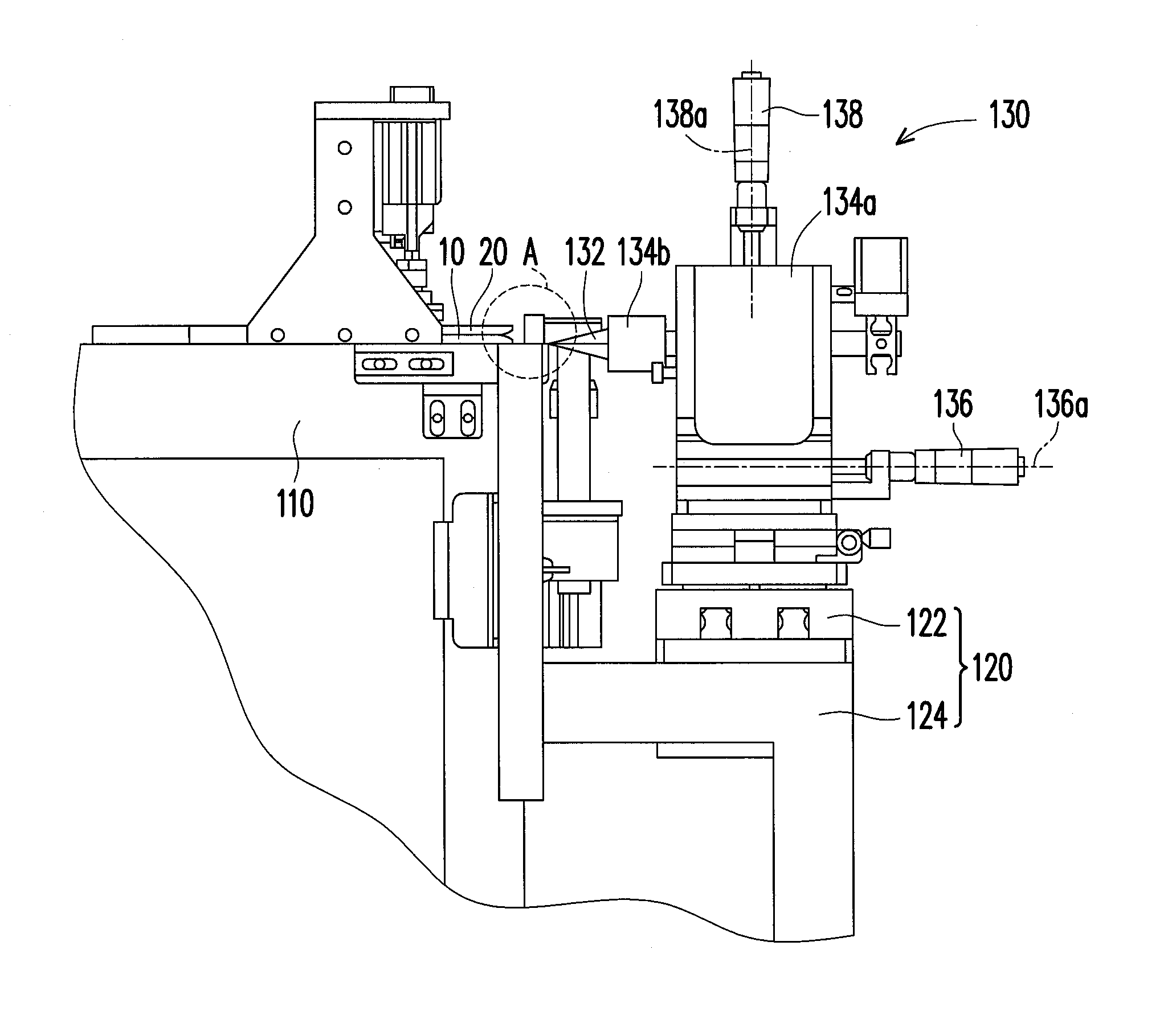
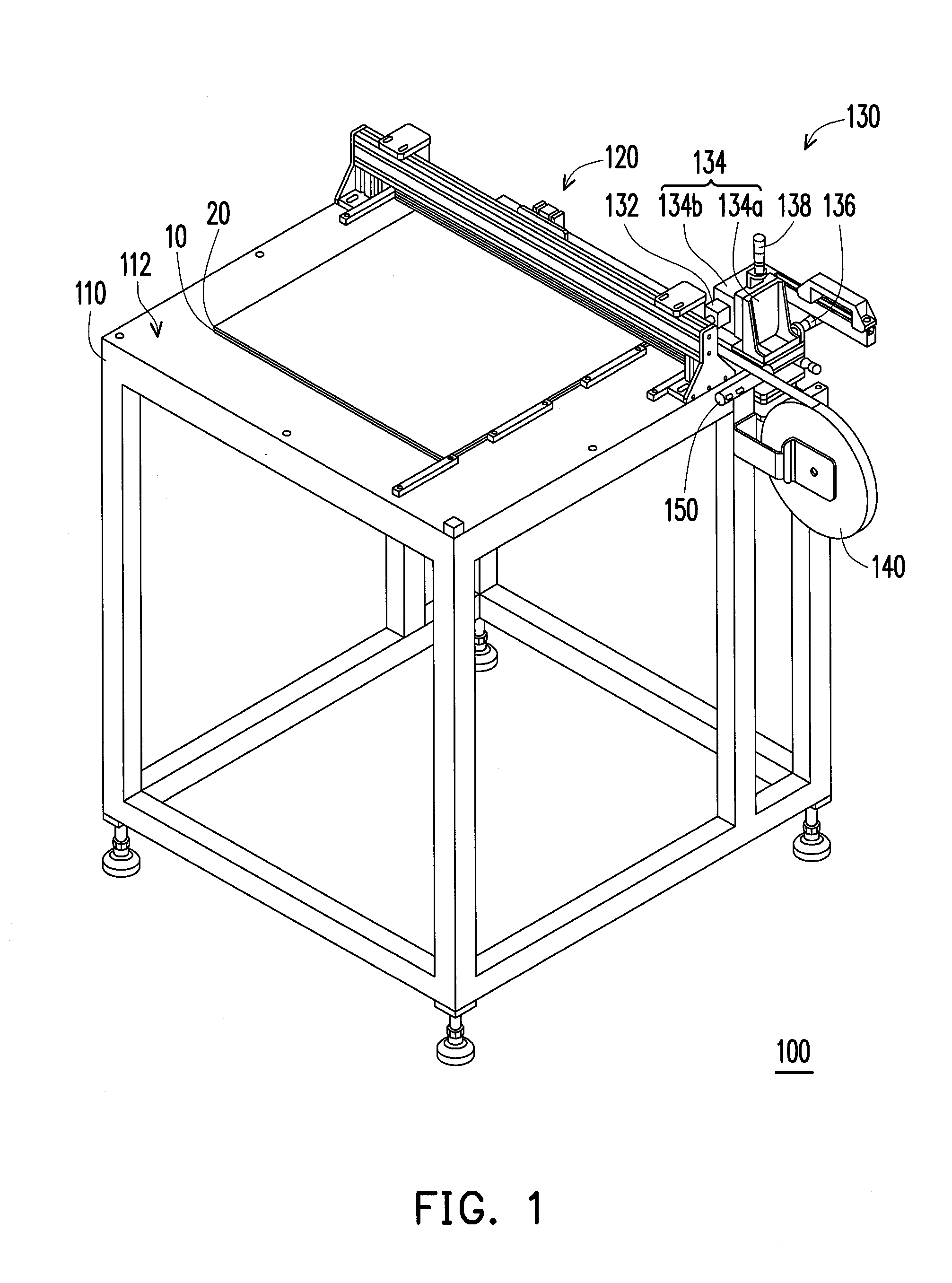
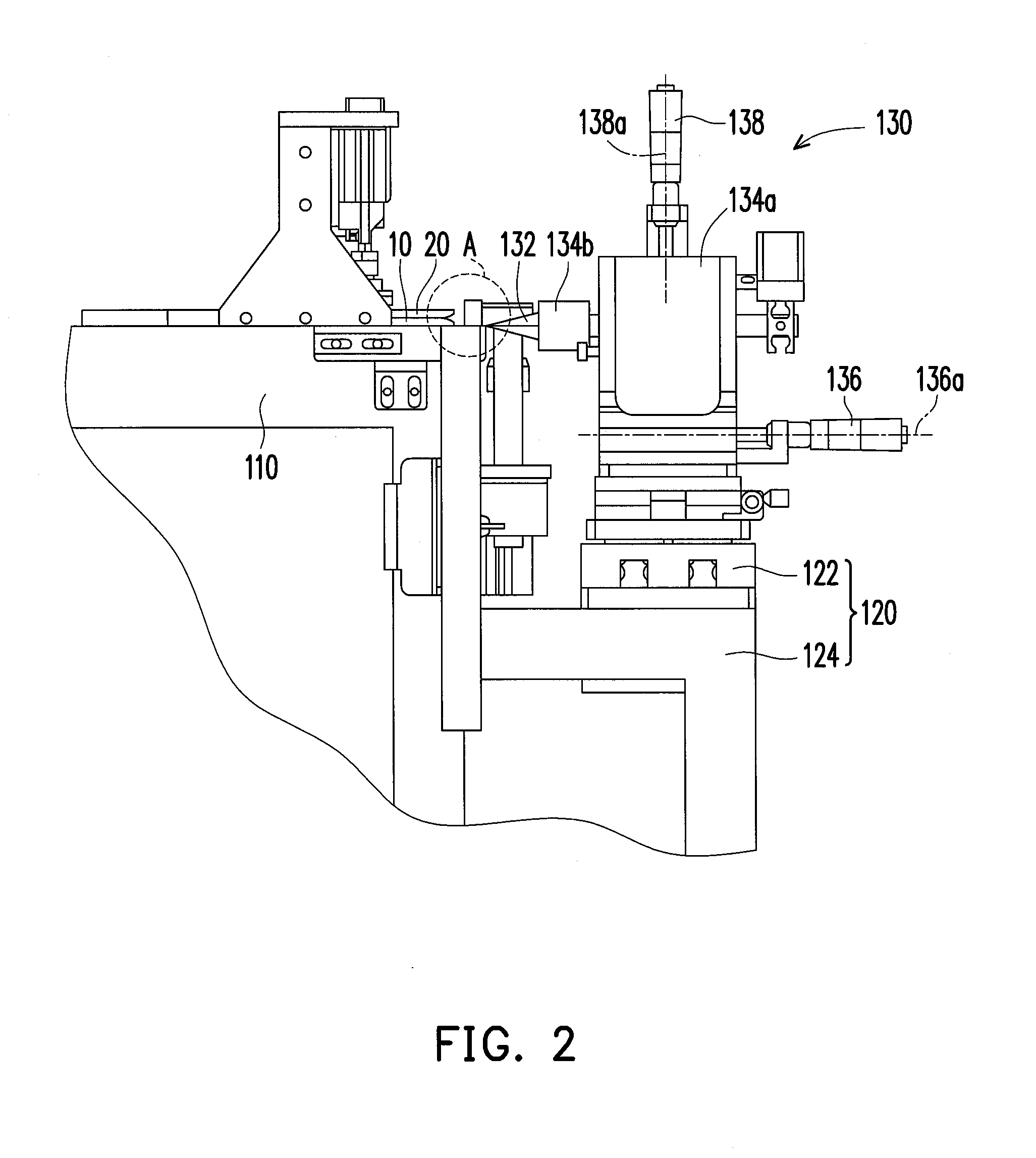
[0034]FIG. 1 is a perspective view of an edge separation equipment of the invention. FIG. 2 is a side view of the edge separation equipment of FIG. 1. FIG. 3 is a partially enlarged diagram of location A in FIG. 2. Referring to FIG. 1, FIG. 2 and FIG. 3, in present embodiment, the edge separation equipment 100 is suitable for a coreless process of a carrier 10 and a circuit board 20. The carrier 10 and the circuit board 20 are attached by a mechanically separable interface 30, and the edge separation equipment 100 is capable of separating the edge of the carrier 10 from the edge of the circuit board 20. In addition, the interface 30 can be a silicone layer, an interface between an ultra-thin copper and a carrier supporting the ultra-thin copper, an interface between stainless steel and electroplated copper, or any other interface which is capable of attaching the carrier 10 to the circuit board 20 or separating the carrier 10 from the circuit board 20. To provide a brief and clear v...
PUM
| Property | Measurement | Unit |
|---|---|---|
| Width | aaaaa | aaaaa |
| Width | aaaaa | aaaaa |
| Width | aaaaa | aaaaa |
Abstract
Description
Claims
Application Information
 - R&D
- Intellectual Property
- Life Sciences
- Materials
- Tech Scout
- Unparalleled Data Quality
- Higher Quality Content
- 60% Fewer Hallucinations
Browse by: Latest US Patents, China's latest patents, Technical Efficacy Thesaurus, Application Domain, Technology Topic, Popular Technical Reports.
© 2025 PatSnap. All rights reserved.Legal|Privacy policy|Modern Slavery Act Transparency Statement|Sitemap|About US| Contact US: help@patsnap.com


